Monday, September 18, 2006

Rear Enclosure Installation - 4 hours (394 Total)

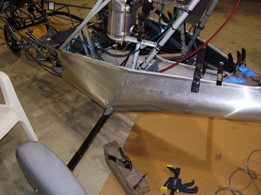
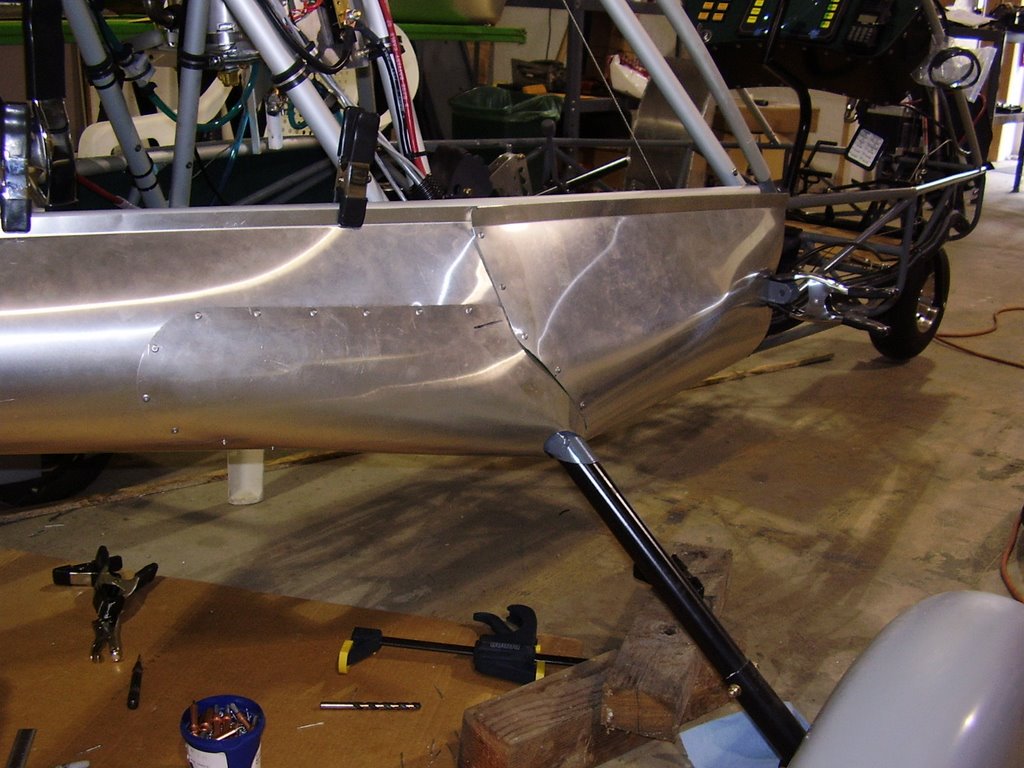
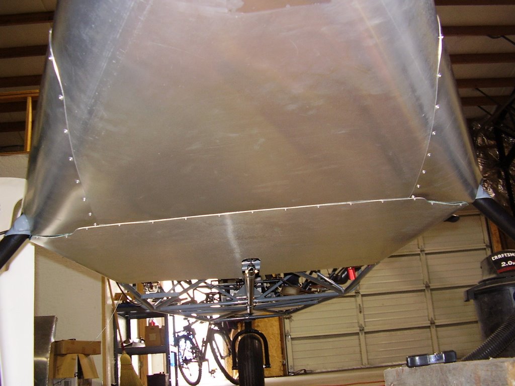
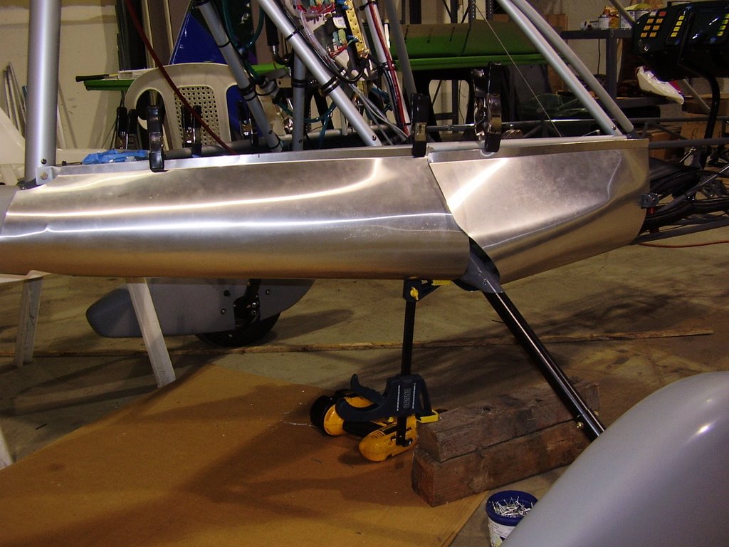
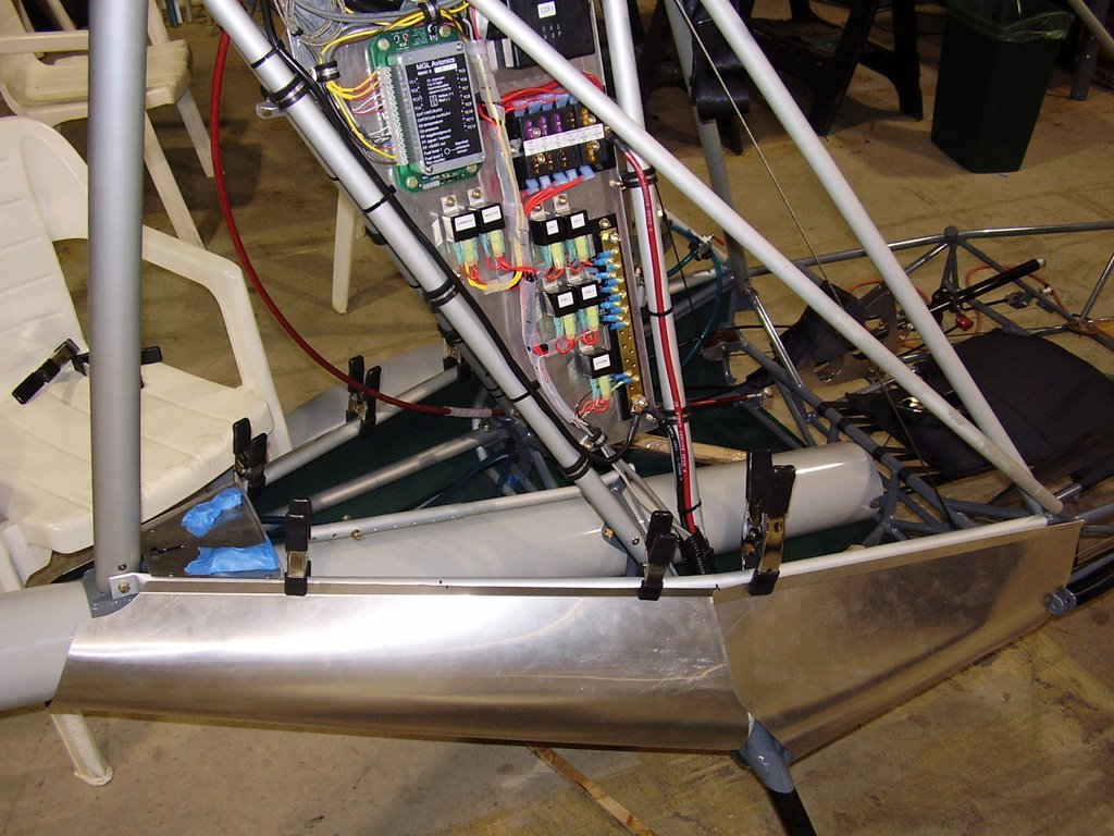
Today I installed the upper panels of the rear enclosure. I started out by taping the edges of the two rear belly pans in place.
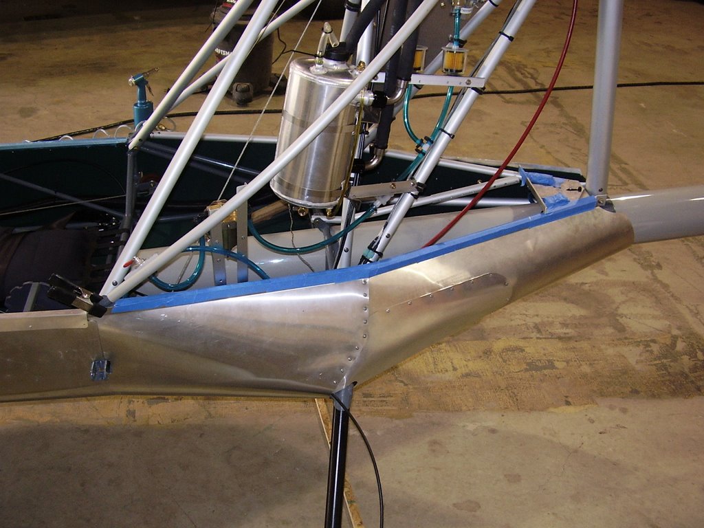


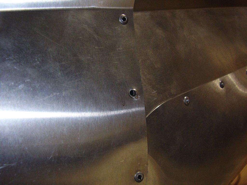
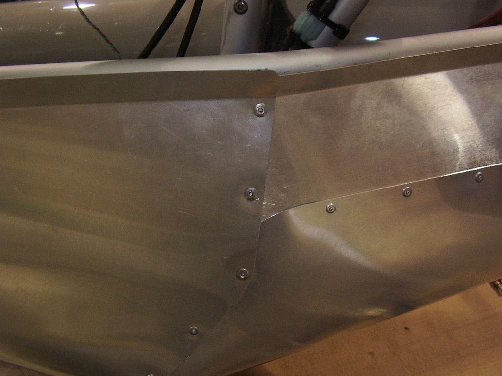
I then positioned the upper panel into place. Getting the right fit was tricky. Once I was satisfied with the positioning, I started drilling and clecoing the bottom edge. I had only drilled my first hole when I realized there was a problem. I had lined up the bottom edge of the upper panel with the crease in the belly pans. This was actually too low and caused the predrilled holes in the upper panel to miss the aluminum tube that I need to rivet into. I repositioned the upper panel and started drilling and clecoing. Unfortunately there is no way to hide that first hole which I drilled in the wrong place.

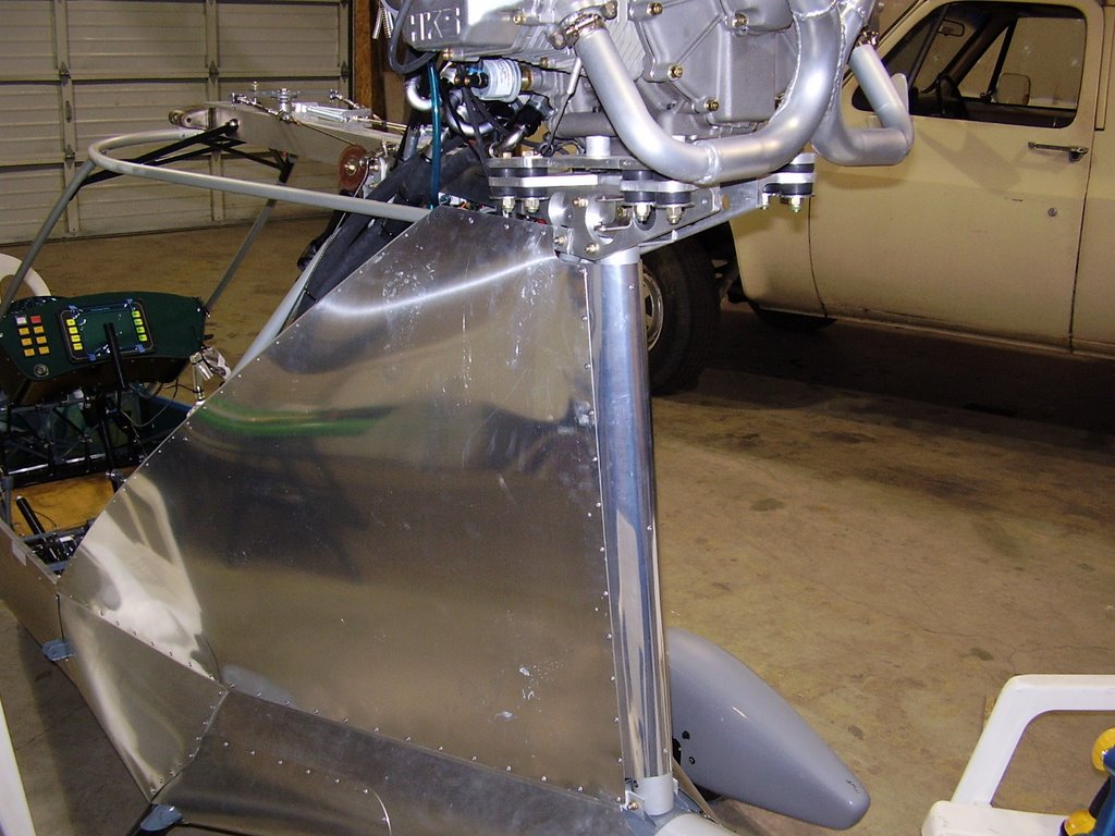
Once I finished drilling and riveting the holes, I attempted to install the upper panel support tubes. I did not like how these tubes are to be attached to the plane. Their straight shape also didn't do much to support the upper panels which naturally curve. I attempted to bent the tubes to fit the contour of the panels without much luck. I decided to omit the support tubes. If necessary, I'll come up with another method to support the panels.

The right panel did not fit as well as the left panel did. With the left panel, the predrilled holes easily lined up with the bottom former tube and the vertical former tube that will also support the lexan. I ended up positioning the panel so the holes in the bottom former need to be angled down in the front, up in the back, and centered in the middle.

The upper edge of both upper panels overlap the top former by a significant amount. This shouldn't interfere with the wing but may cause problems with the fuel lines. I may need to trim or add rubber trim to the panel if the fuel lines come in contact with it.
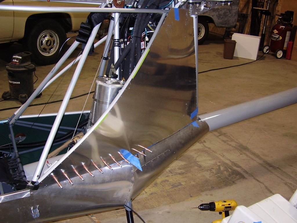
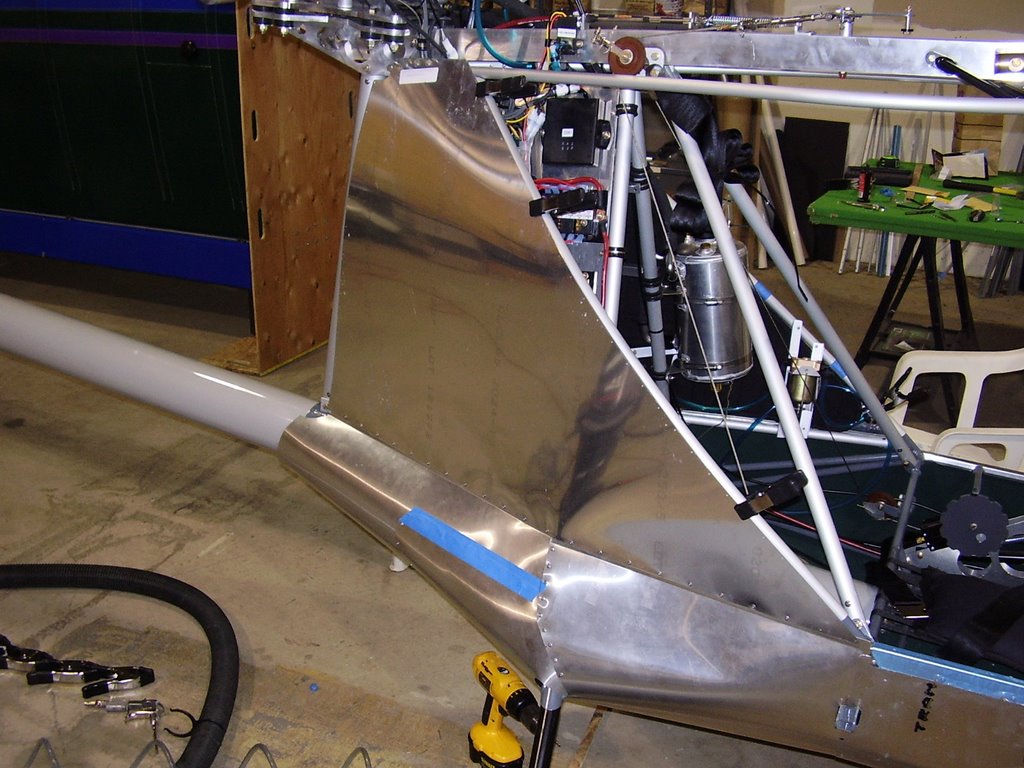


Once the two upper panels were riveted into place, I installed the rear enclosure. This pre-bent piece easily fit into place. The top edge of the rear enclosure revealed that the top edges of the two upper panels are off by 1/8". I positioned the rear enclosure to be flush with the right side. I also needed to ensure that the inside edges of the rear enclosure was tucked between the upper panels and the sound proofing inside the plane.


Belly Pan Cover - 4 hours (390 Total)

Well I didn't get the plane over to the painter yet. I still have quite a bit to do. Luckily the painter is behind schedule also.

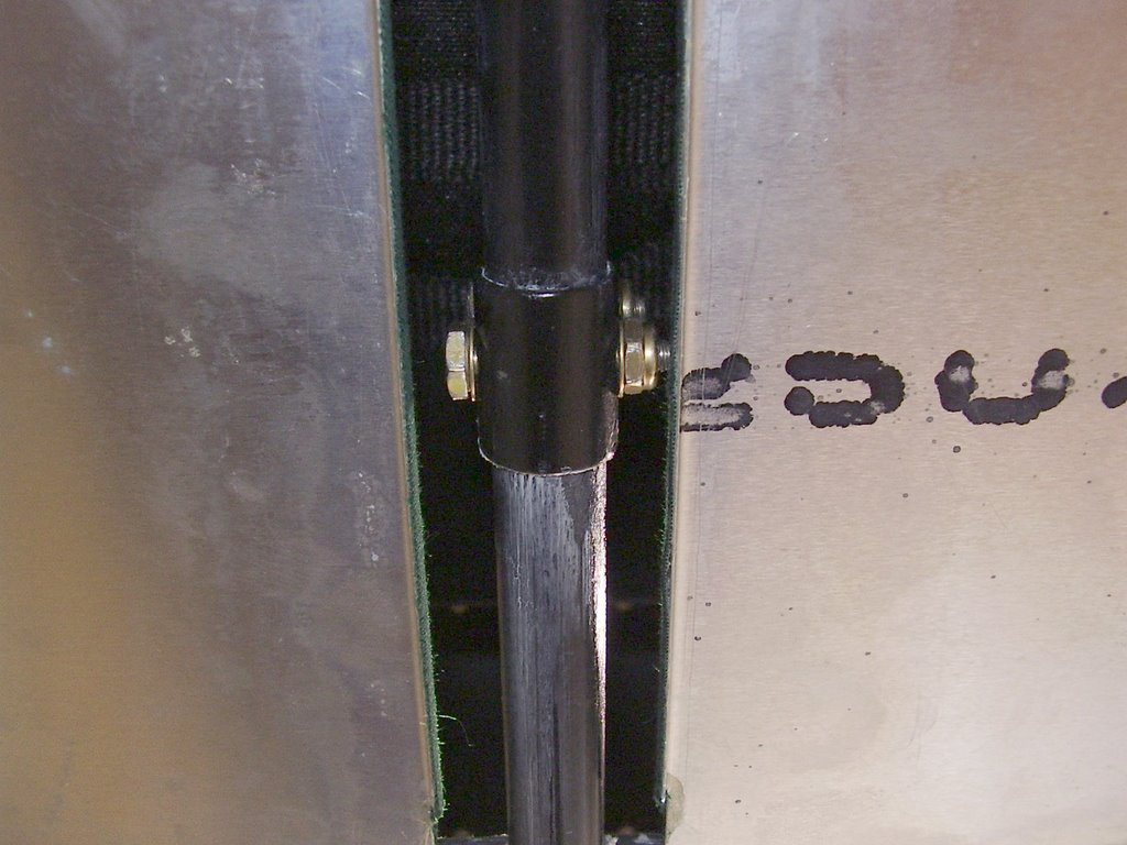
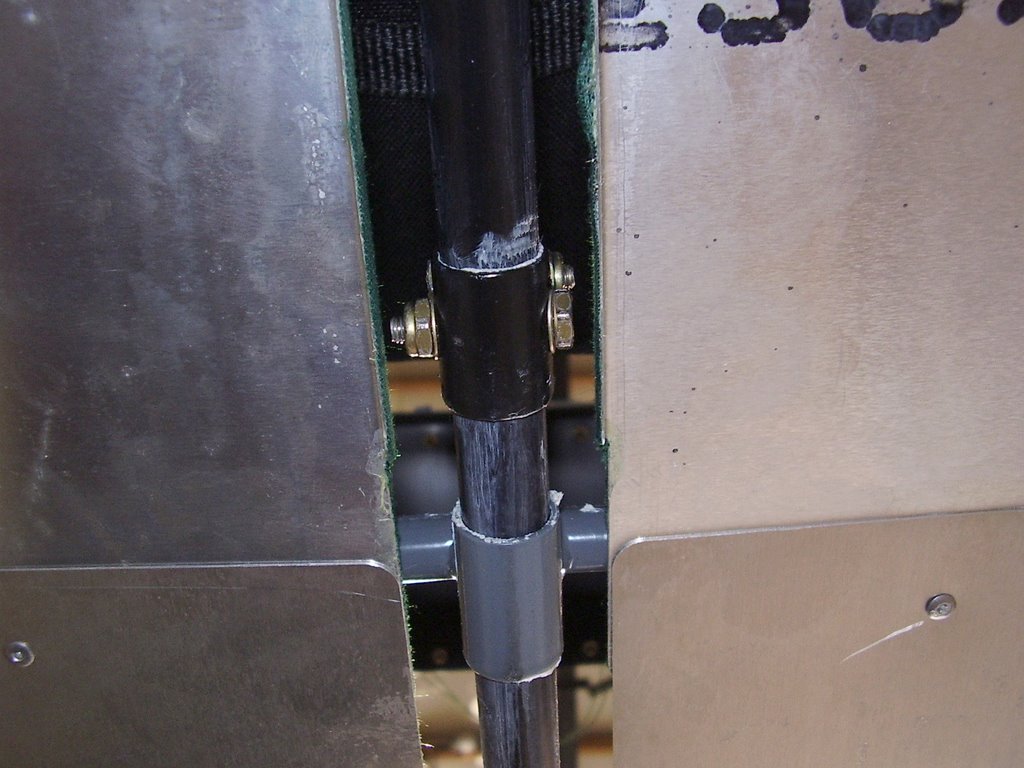
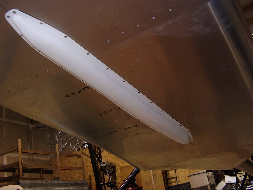
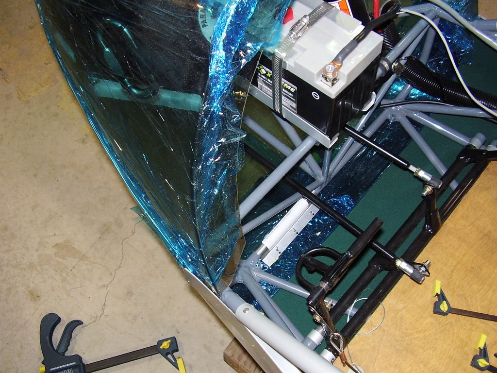
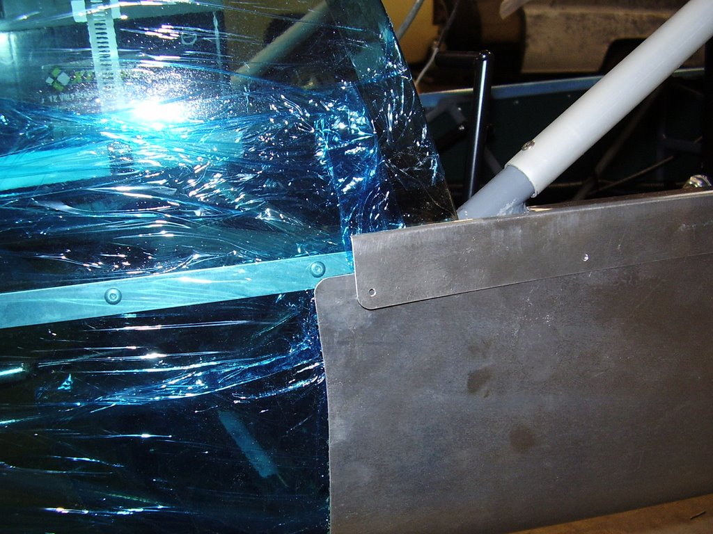
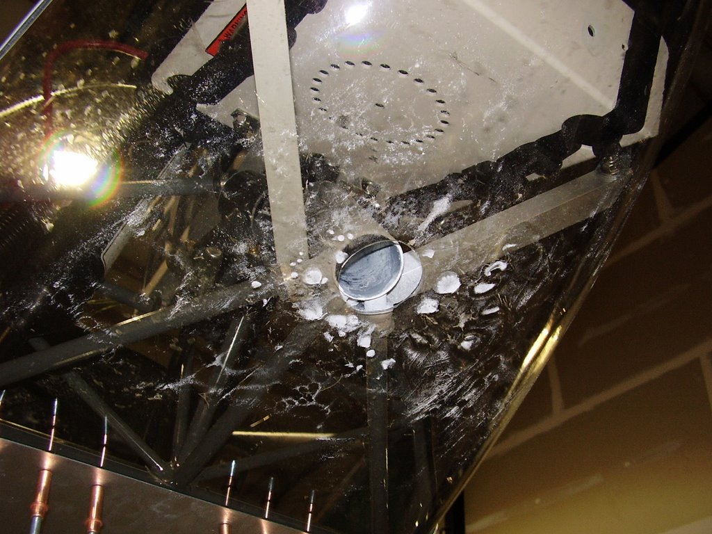
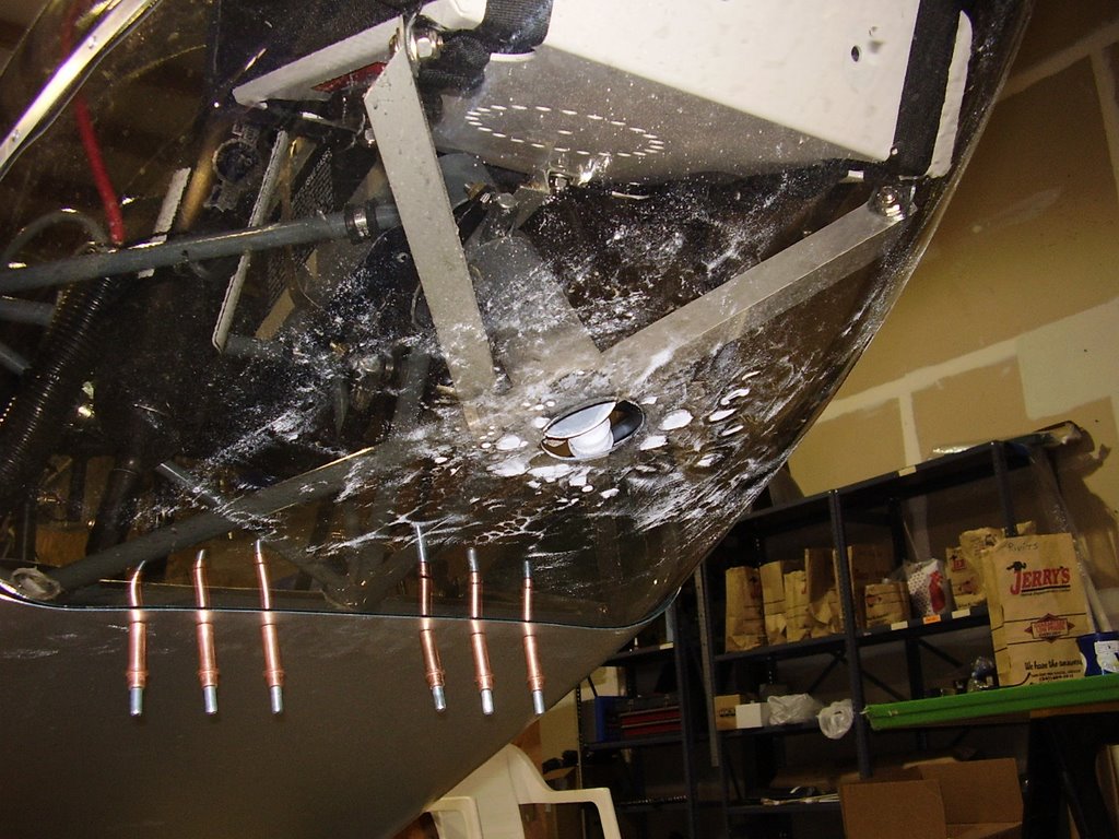
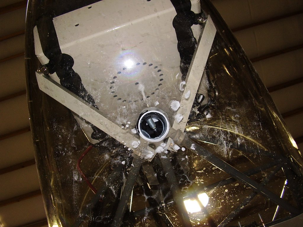
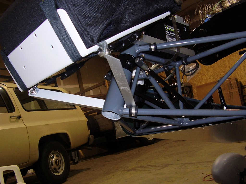
My first task is to install the belly pan cover. I had the painter paint the inside of this plastic cover with a green that matches the interior fabric. While I was placing the belly pan cover to check for proper fit, I noticed that the push pull tube that it is suppose to cover is having some slight rubbing issues. It turns out that the bolt is just barely rubbing on one of the belly pans. To fix this I removed the bolt and installed it from the other side. You can see from the before and after photos below that there is about a sixteenth of and inch more clearance on one side of the tube than the other.


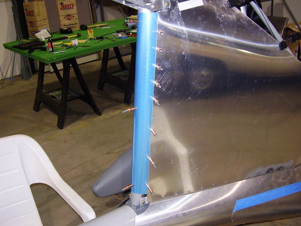
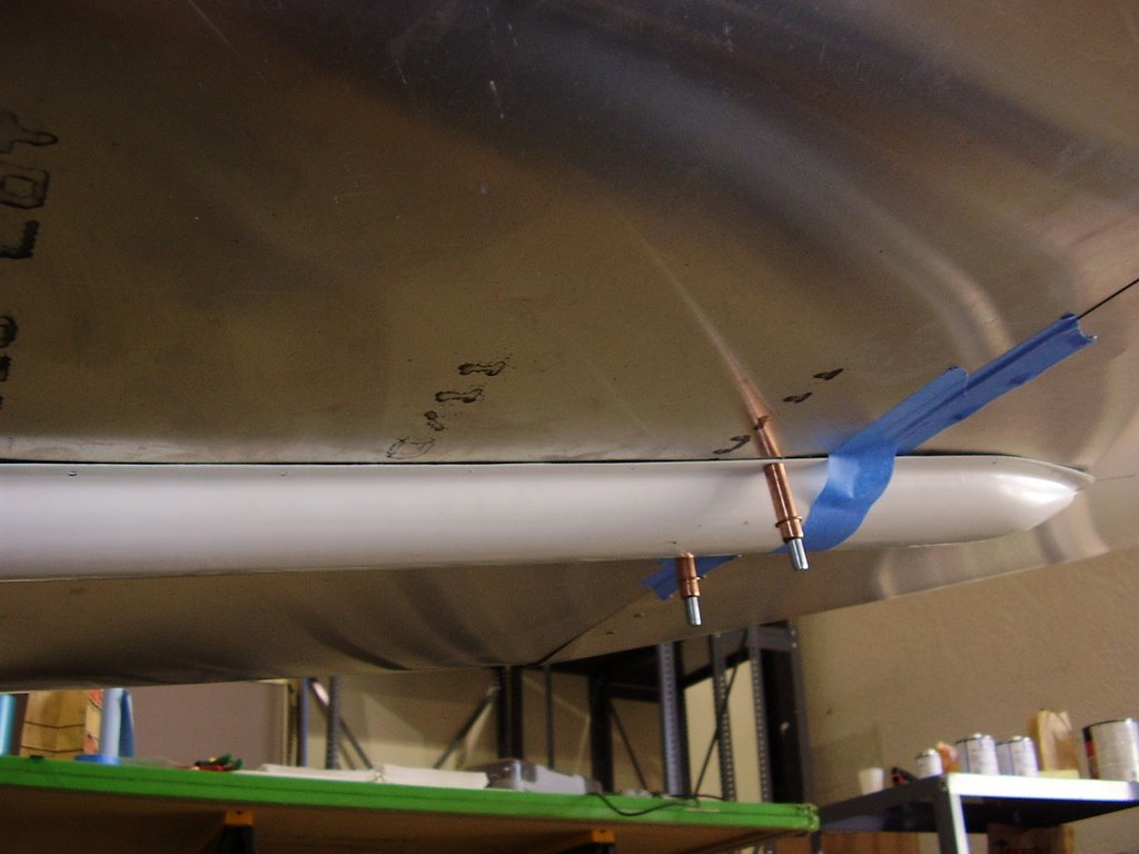
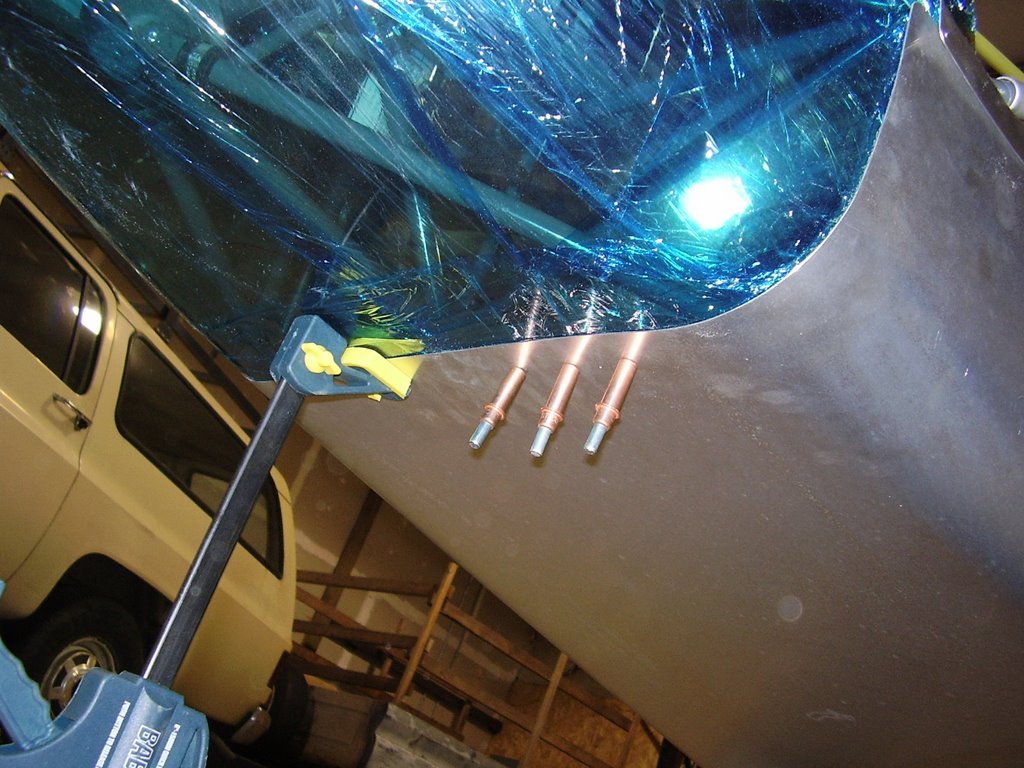
To installed the belly pan cover I first marked my proposed holes into the cover and made sure there was clearance in the plane for the rivets. I ended up having some problems with the rivets interfering with the end of the tail boom. I ended up drilling my holes into to the tail boom to allow the rivets to recess into it.

I predrilled all the holes with a #40 drill bit and then drilled through the pan cover and the belly pans with the proper #30 bit while positioning the pan cover in place using masking tape and clecos. I worked from the middle out to allow for the plastic pan cover to distort around the slight curvature (forward to back) of the bottom of the plane.


Sunday, September 17, 2006

Nose cone Installation - 12 hours (386 Total)

Today was another long day. My goal is to get the enclosure finished so I get take the plane to the painter's place on Monday (tomorrow).

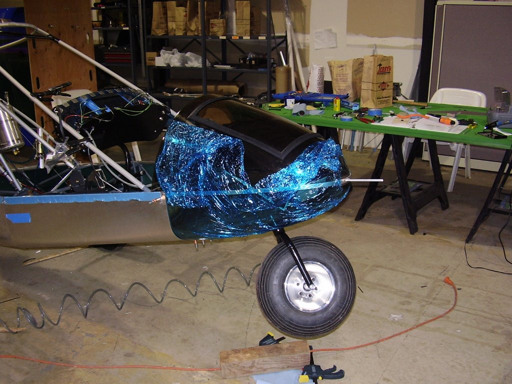
Today I focused on the nose cone. The first step was to correctly position the nose cone. The nose cone needs to be inline with the longerons and be 55 1/8 inches from the keel tube. This was simple enough to set but required grinding away some of the nose cone to allow it to fit around some of the weld joints in the frame.
Once the position was set, I drilled and cleco'd the metal strips that hold the bottom of the nose cone and the forward most belly pan to the steel frame.


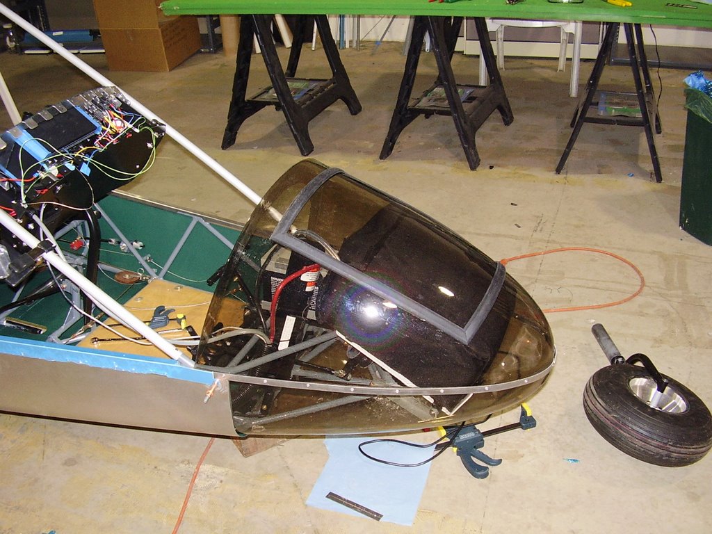
The way the longeron rails, forward most belly pan, and the metal strip around the nose cone meet was difficult to determine. Once this was determined I drilled and cleco'd through the three to hold the nose cone in place. Below is a photo of what I ended up with.


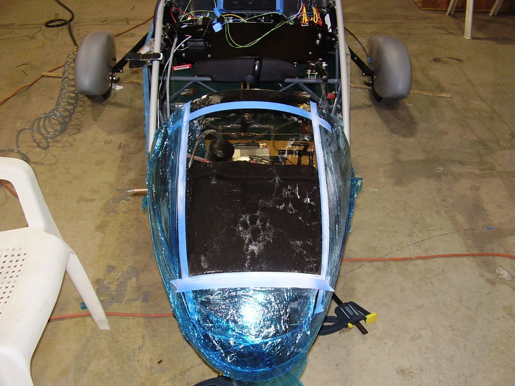
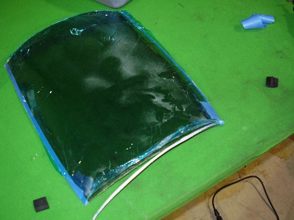
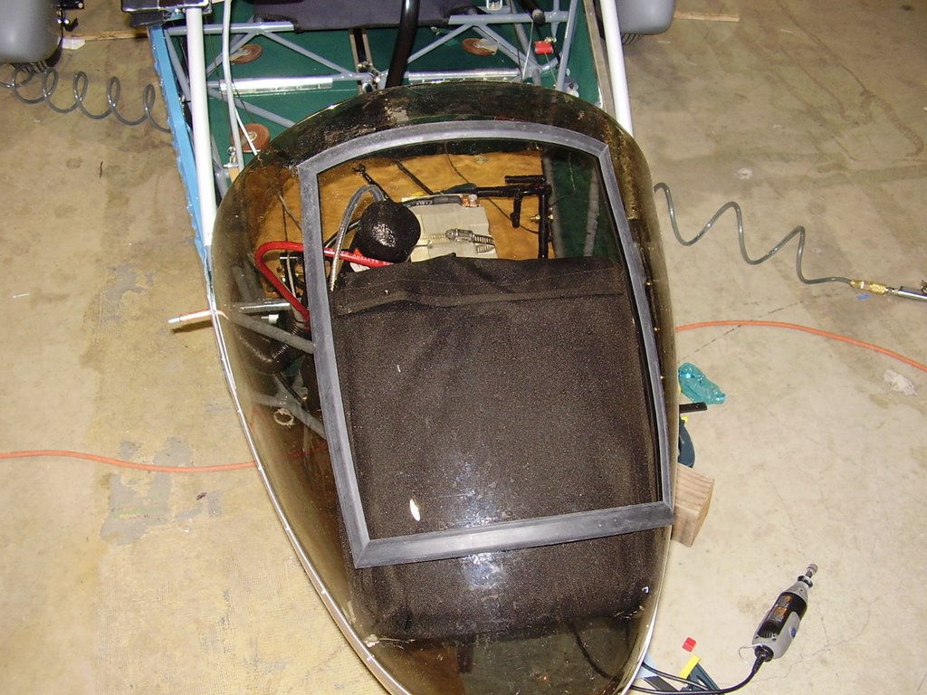
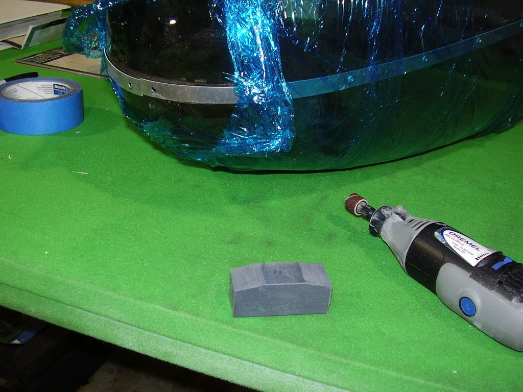
Now that the nose cone placement is set, I need to cut out my blow out panel for my parachute. I used my Dremel tool to cut out the panel once I was satisfied with my cut out outline placed with masking tape.


Once the panel was cut out, I then trimmed off 3/16 of an inch off on all four sides. This will allow room from the center portion of the H-channel rubber trim I bought.


It was a little bit of a wrestling match to get the blow out panel back in place with the trim but it does have a good tight fit. The channels of the rubber trim are a little larger than I had hoped for. The Lexan material of the nose cone doesn't fill the channel completely but it should work. I may try to glue the channel to the top surface of the nose cone and the blow out panel.


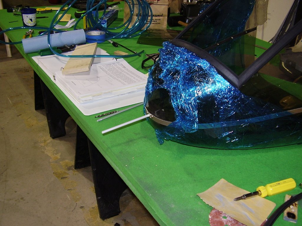
Now for the nose wheel... Again I used my Dremel to grind a hole in the bottom of the nose cone for the nose wheel. I oversized the hole to allow a 1/8 inch gap between the nose wheel fork and the Lexan.


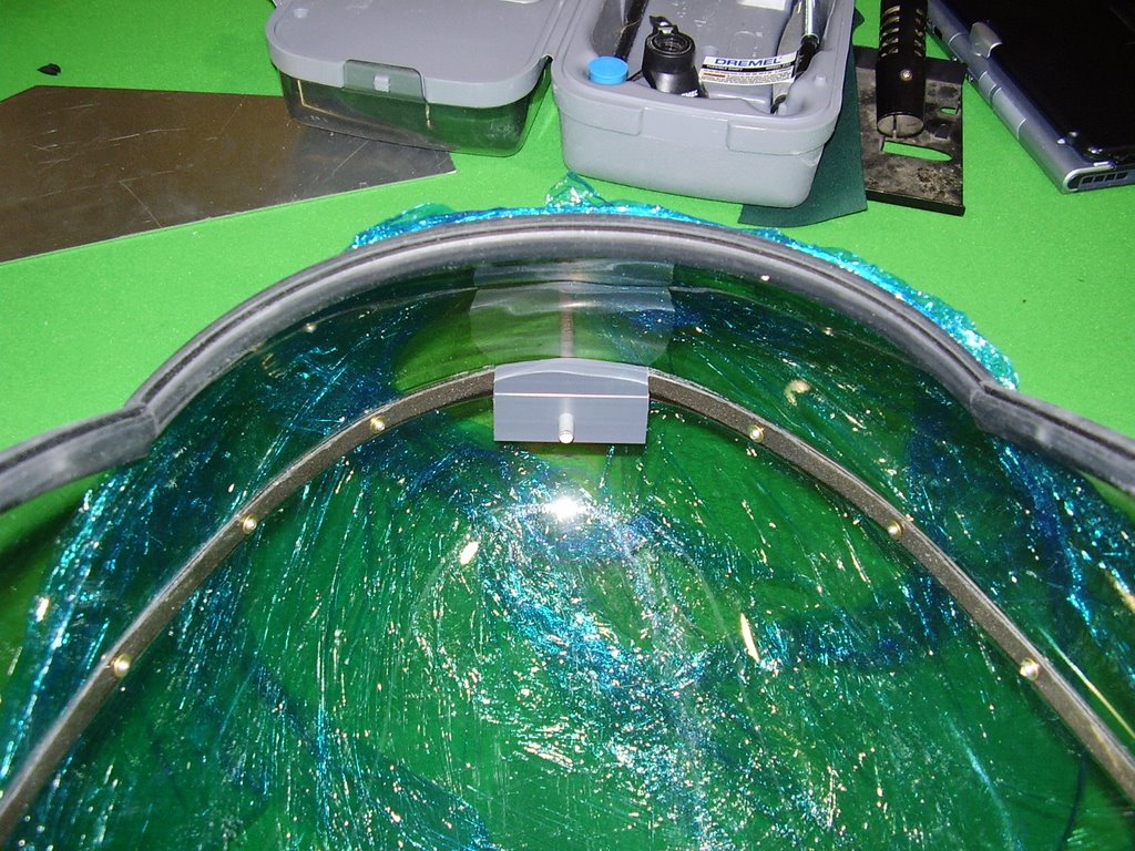
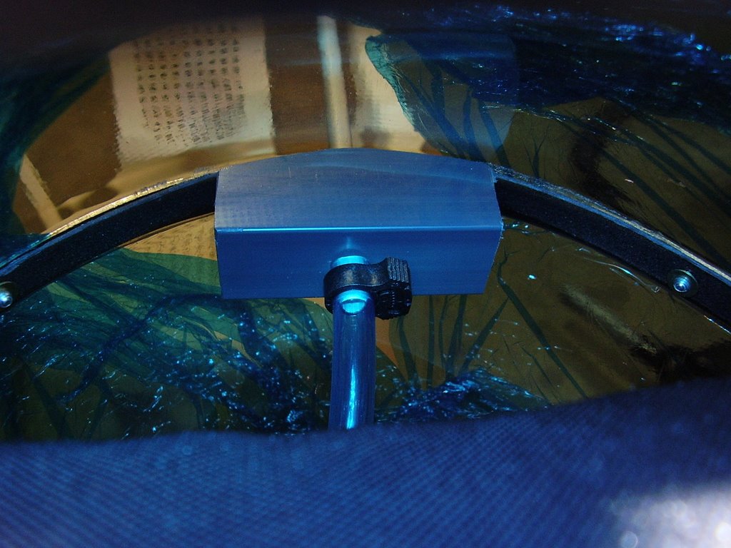
My next task was to install my pitot tube. I started out by predrilling a hole through the pitot tube mounting block. I drilled this hole one size smaller that the 1/4" pitot tube. I them contoured the block to fit well with the inside of the nose cone. I then screwed the block in place and drilled the 1/4" hole through block and nose cone. I then removed the block and attempted to install the pitot tube into the block. The hole was too tight and I ended up damaging the pitot tube. Luckily, I had another tube I could use. I partially drilled out the block with a slightly larger drill bit. This allowed me to install the pitot tube and still have a enough retention force.


I then drilled out a 5/8" hole in the two inch flange on the top half of the nose cone. I placed a rubber grommet into the hole and threaded my pitot tube through it. This will hold my pitot tube nicely. My first attempt in drilling the grommet hole ended up being too large so I ended up having to drill a second hole.


Just prior to permanently installing my nose cone, I cleaned out the grease for the nose wheel fork and replaced it with some clean grease. I then installed and riveted the nose cone into place. I then installed the nose wheel fork and bolted it into place. This was easier than I had expected. I was able to work around the battery, rocket, and parachute easily from the left side. It will be a different story once I get the windshield installed.


Saturday, September 16, 2006

(More) Belly Pan Installation - 12 hours (374 Total)

Today was a long day but I was able to get the rest of the belly pans installed.

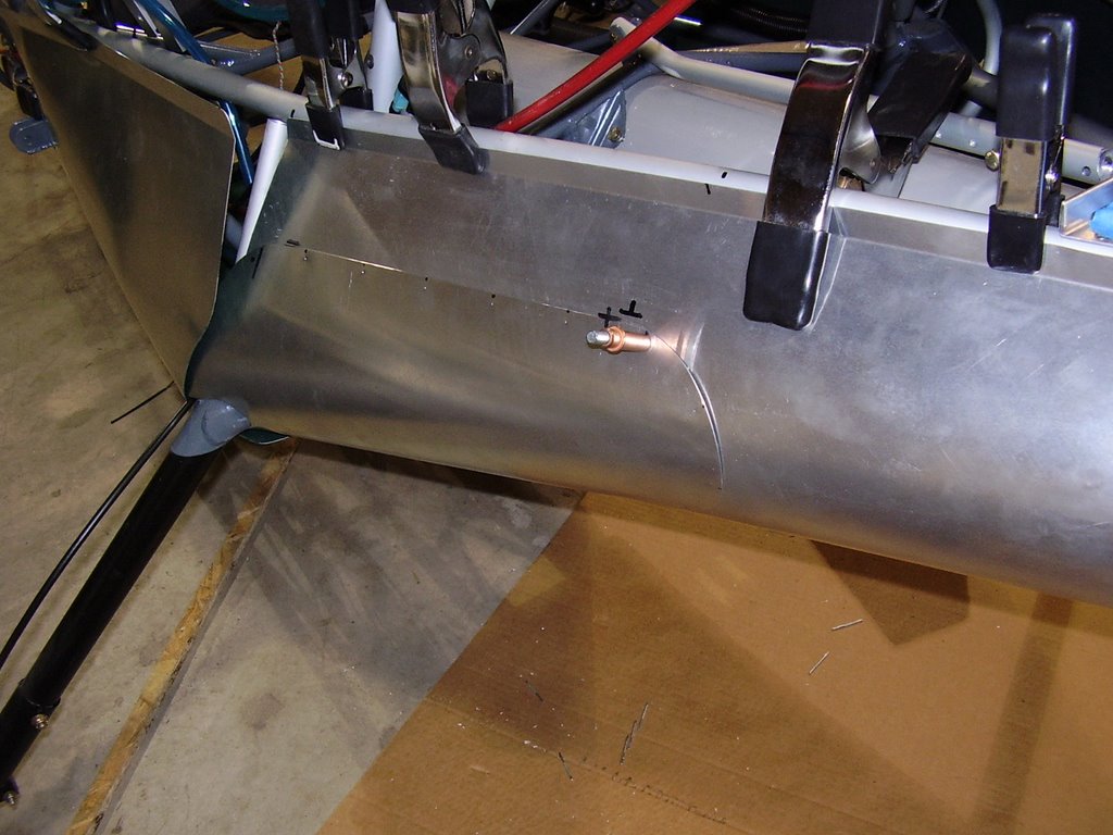
The first thing I did was start installing the landing gear cuffs. These are used to cover the large hole between the two rear most belly pans. There isn't much to go by in terms of how to position these so I made the top edge of the cuffs parallel with the seam of the rear most panel. Below are a couple pictures of the cuffs.


The picture below shows an enlarged rivet hole. Not liking the look of how the belly pans were riveting together, I drilled out a couple of rivets to replace. Unfortunately, the hole in the sheet metal enlarged to the point that I was having trouble with the rivets. To alleviate this I purchased and used some slightly larger rivets.


Here are some other pictures of cuffs in various stages of the install.


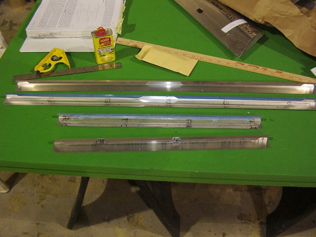
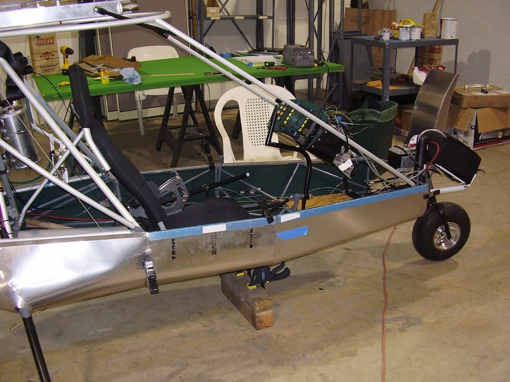
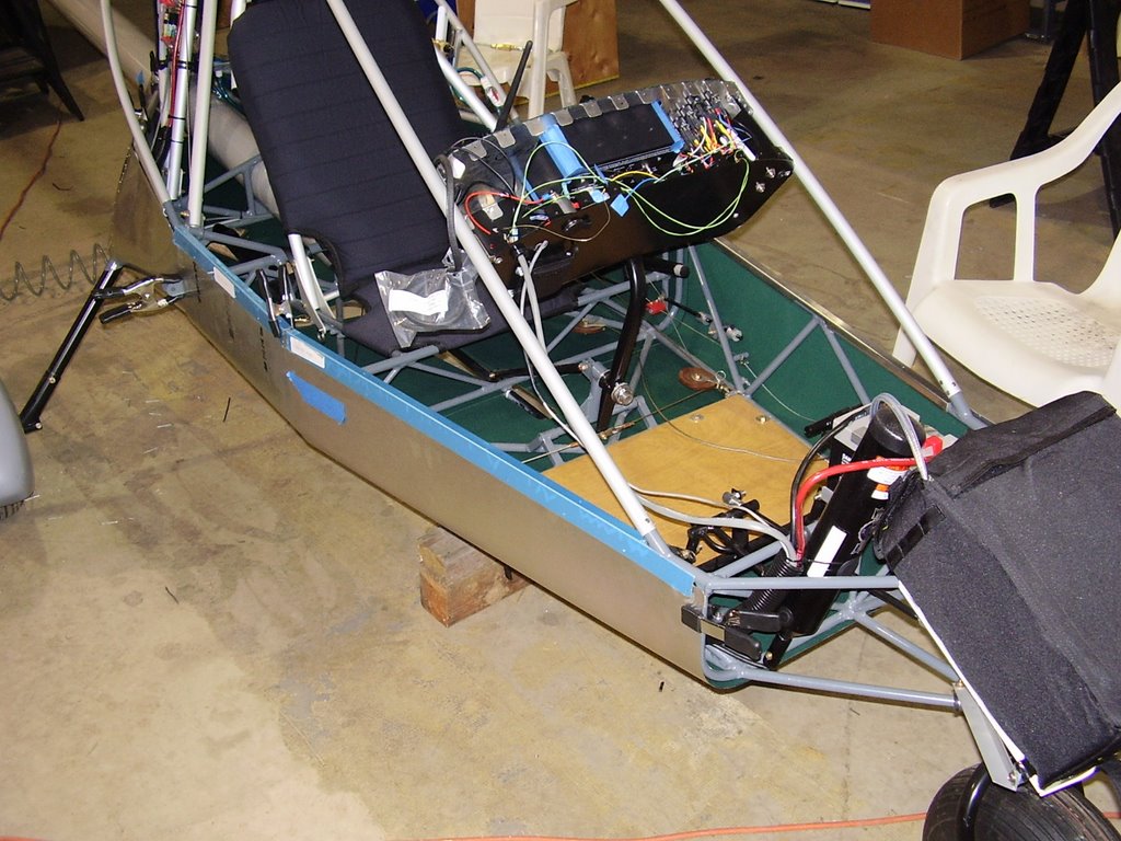
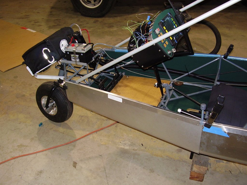
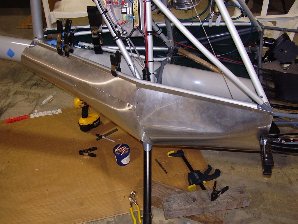
Next came the front two belly pans. The pan that fits below the seat is actually two pans, a left and a right. These three pans are attached to the frame by rails that fit over the longerons of the steel frame. The pans are then riveted to the rails.


All but one of the rails needed to be modified to allow it to fit around welded points on the frame.


Below are some pictures of the front two belly pans and their accompanying rails. I permanently riveted the rails on the right side of the plane but only used some #40 temporary rivets to hold the rails on the left side. These will be permanently riveted when the windshield is installed.


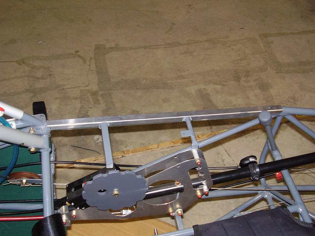
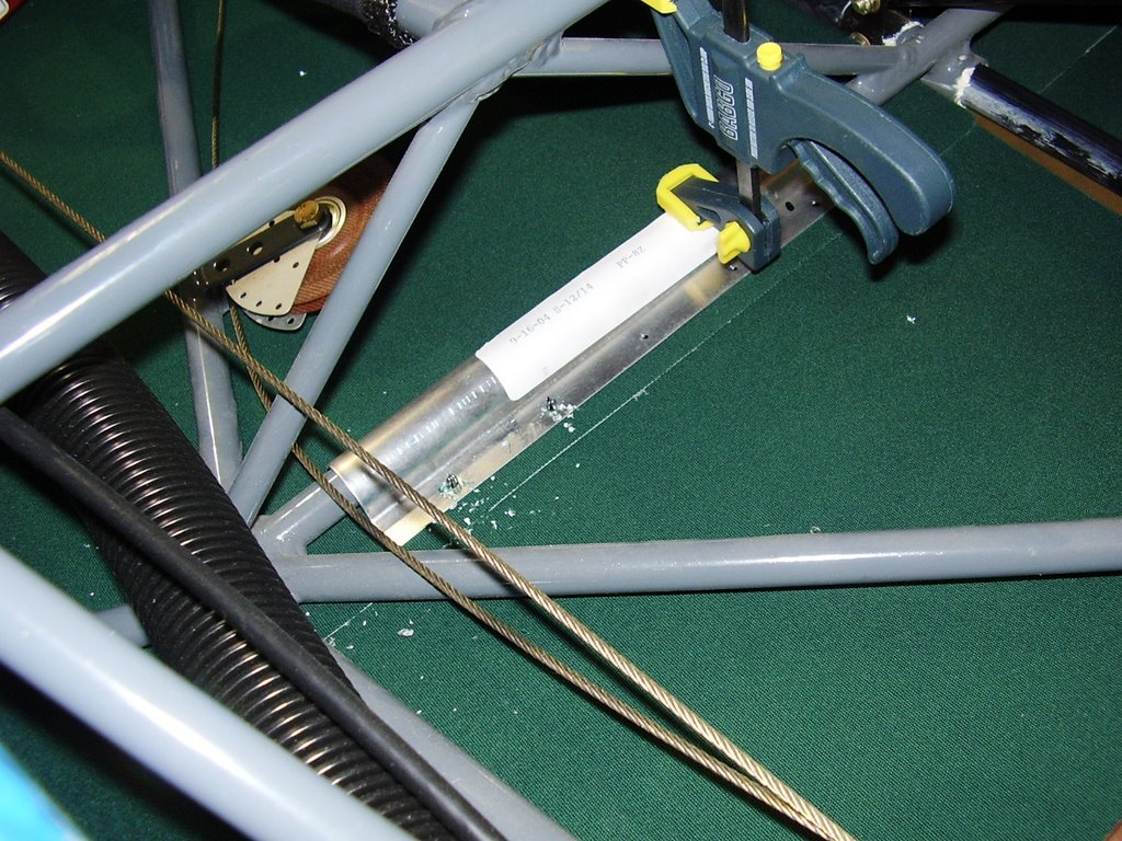
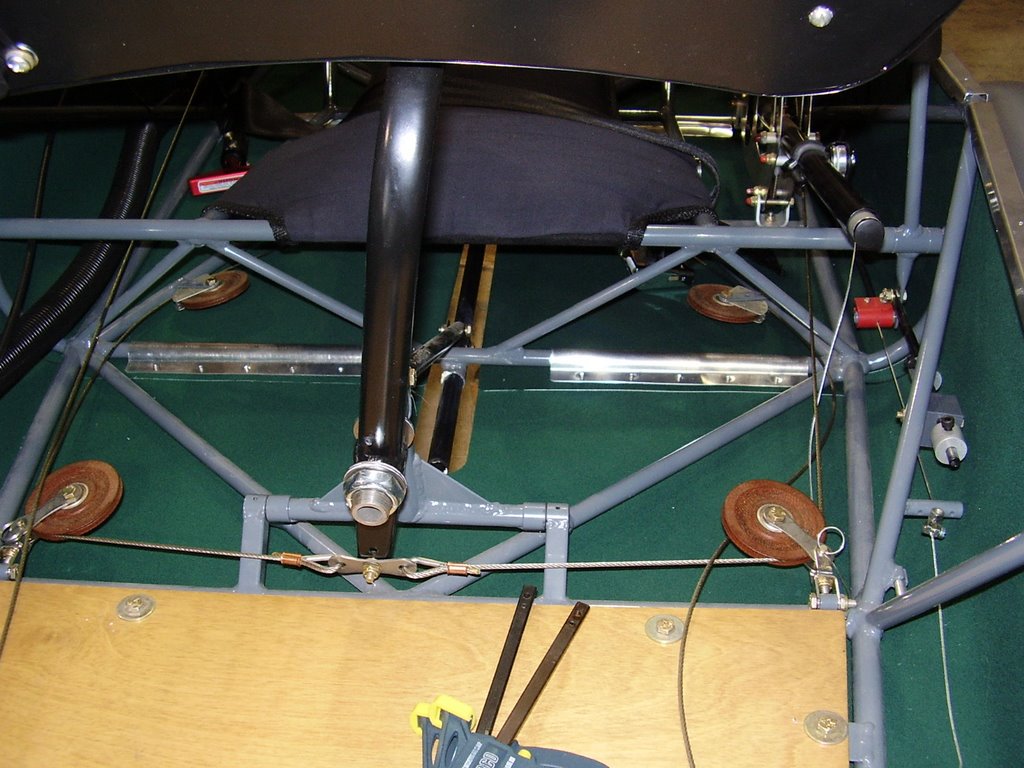
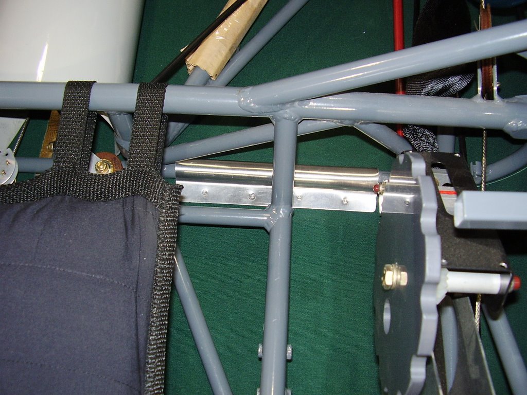
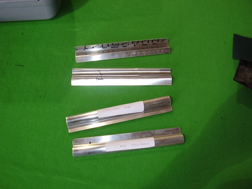
The belly pans are held in place to the bottom of the plane with the metal pieces pictured below. They fit over the horizontal members of the steel frame and are riveted to the belly pans at the belly pan seems. Prior to riveting these in place I deformed them slightly so they grip the frame and sheet metal tightly.


The piece below needed to be trimmed to fit around the weld that holds the flap lever bracket in place.


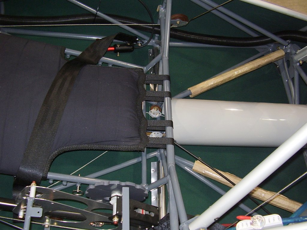
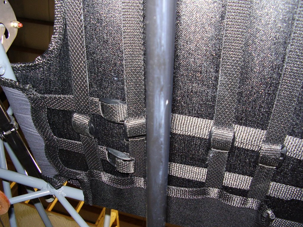
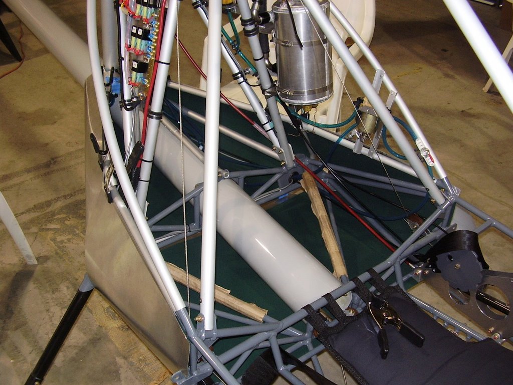
Prior to fully installing the belly pans, I tightened the straps on the seat bottom. This is my last, easy opportunity to tighten these straps.

Friday, September 15, 2006

Belly Pan Installation - 5 hours (362 Total)

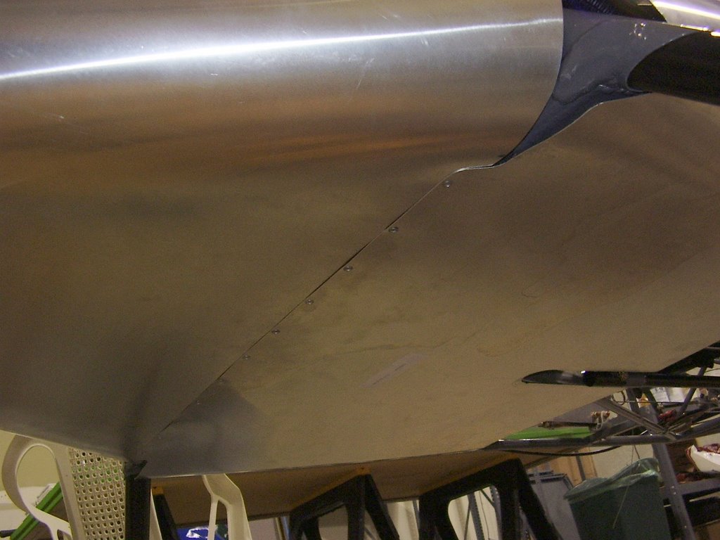
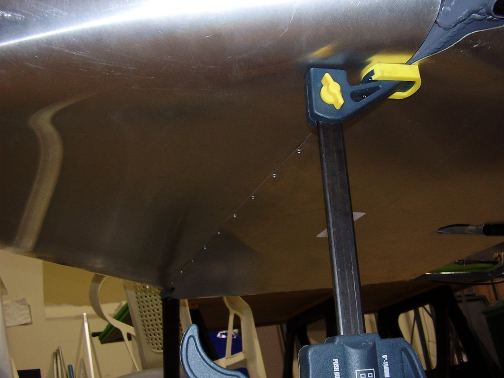
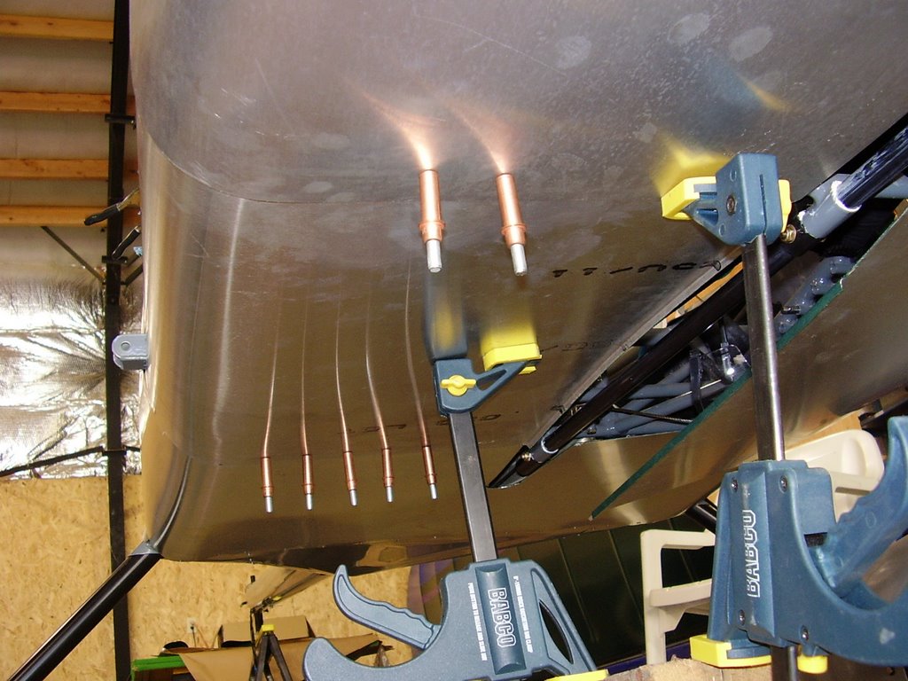
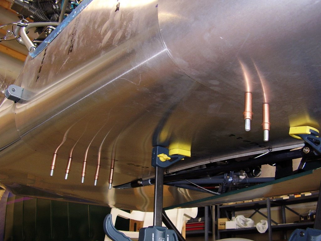
Today I installed the two rear most belly pans. This took an incredibly long amount of time to get the placement just right. Once I started riveting the two pieces together, I used a set of reversible clamps to hold the sheet metal in place.