Thursday, June 08, 2006

Exhaust - 4.5 hours (279.5 Total)

Earlier this week I received my exhaust from Earthstar. Below are some pictures and details of its installation.


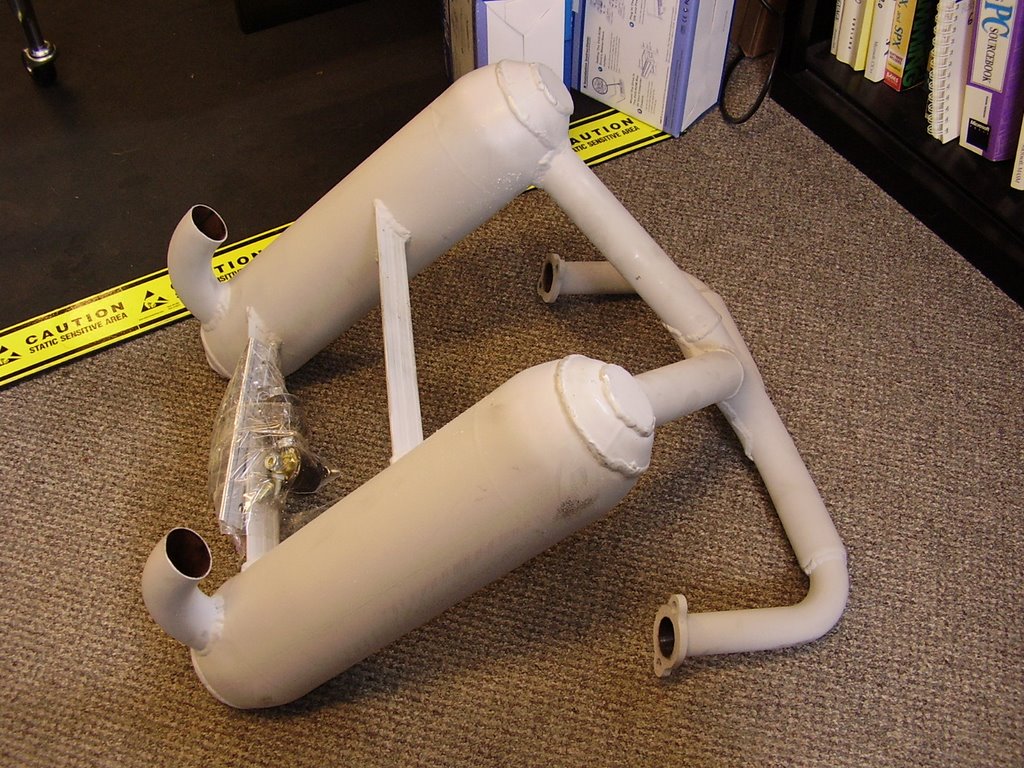
I purchased an exhaust from Earthstar that was already ceramic coated. Unfortunately, no finishing was done after the coating was applied.


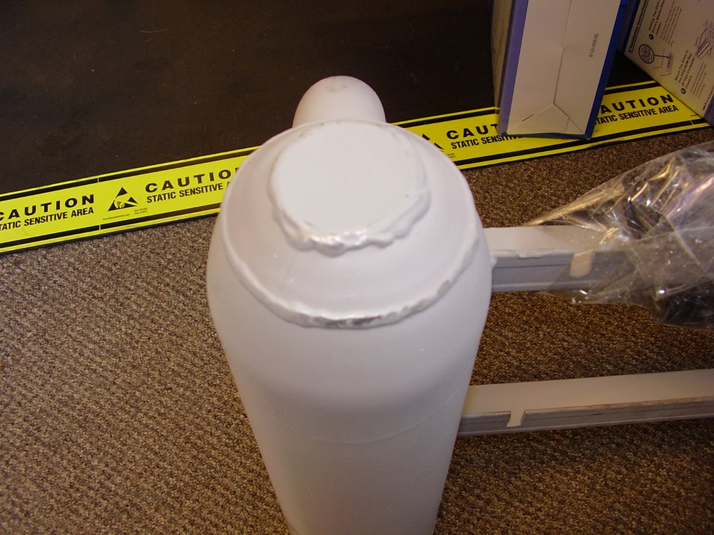
I would have been happy with the light gray coloring and powdery texture but the exhaust had several polished spots on it. During shipping, portions of the exhaust that were in contact with the cardboard box or styrofoam polished themselves due to the vibrations.


Another problem with the unpolished ceramic coating is that it picks up dirt very easily. There were hand prints on the exhaust left by the Earthstar people.


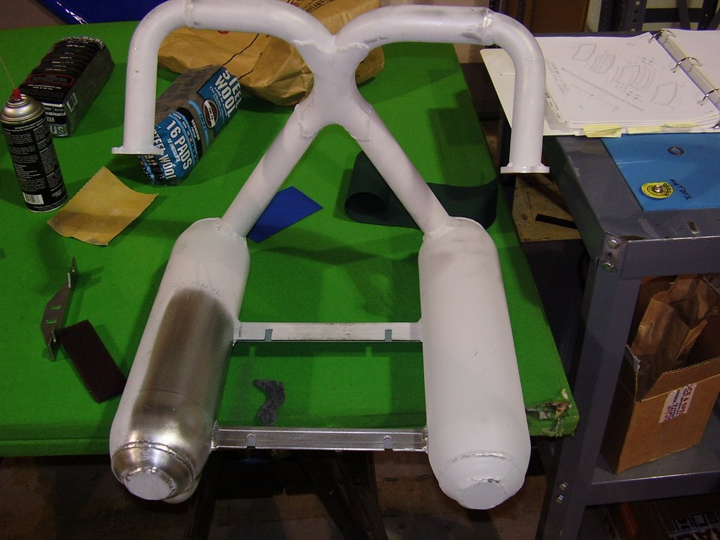
After consulting with Earthstar and Finish Line Coatings, a company in Portland, OR that does ceramic coatings, I started polishing the exhaust with some steel wool. This was surprisingly easy to do.


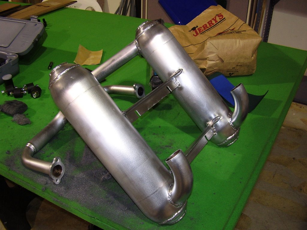
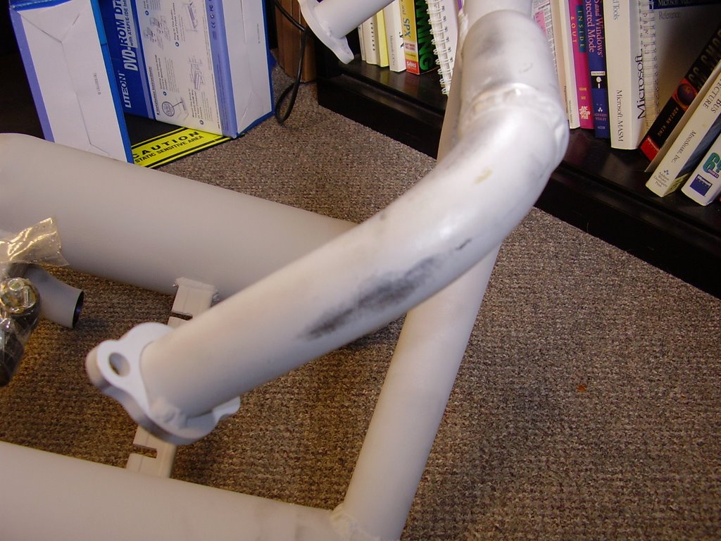
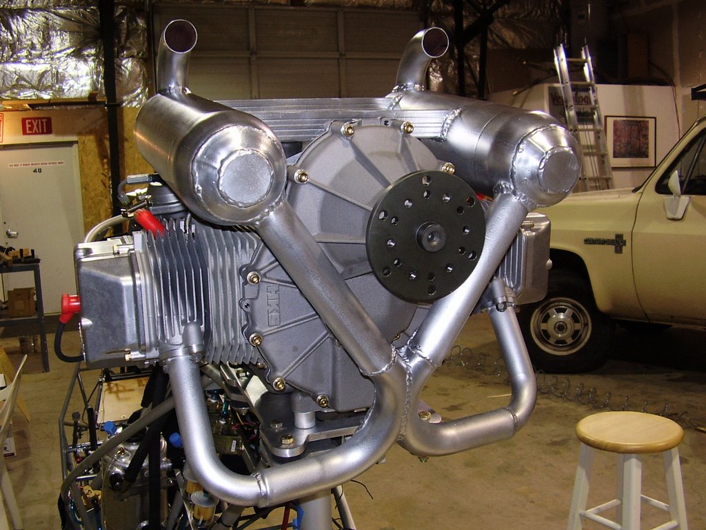
Here is a picture of the fully polished exhaust. It took me about three and a half hours to polish the entire exhaust.


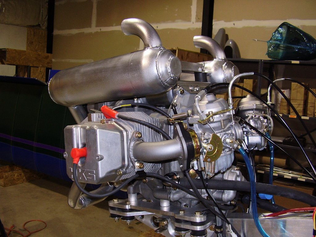
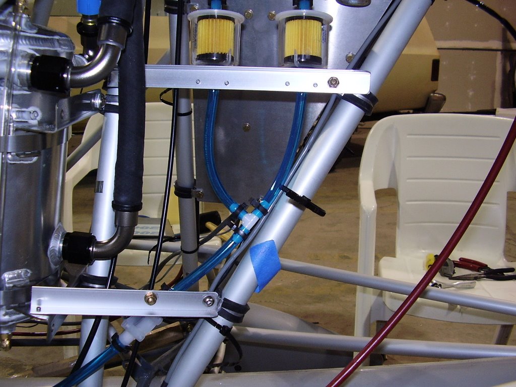
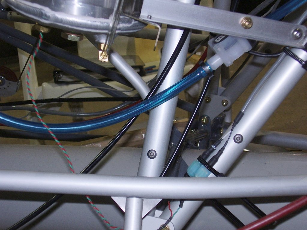
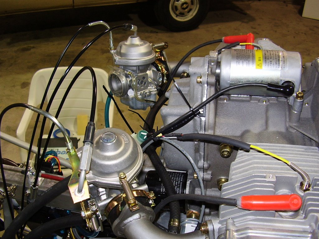
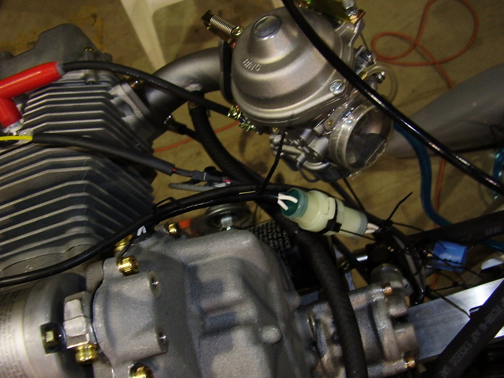
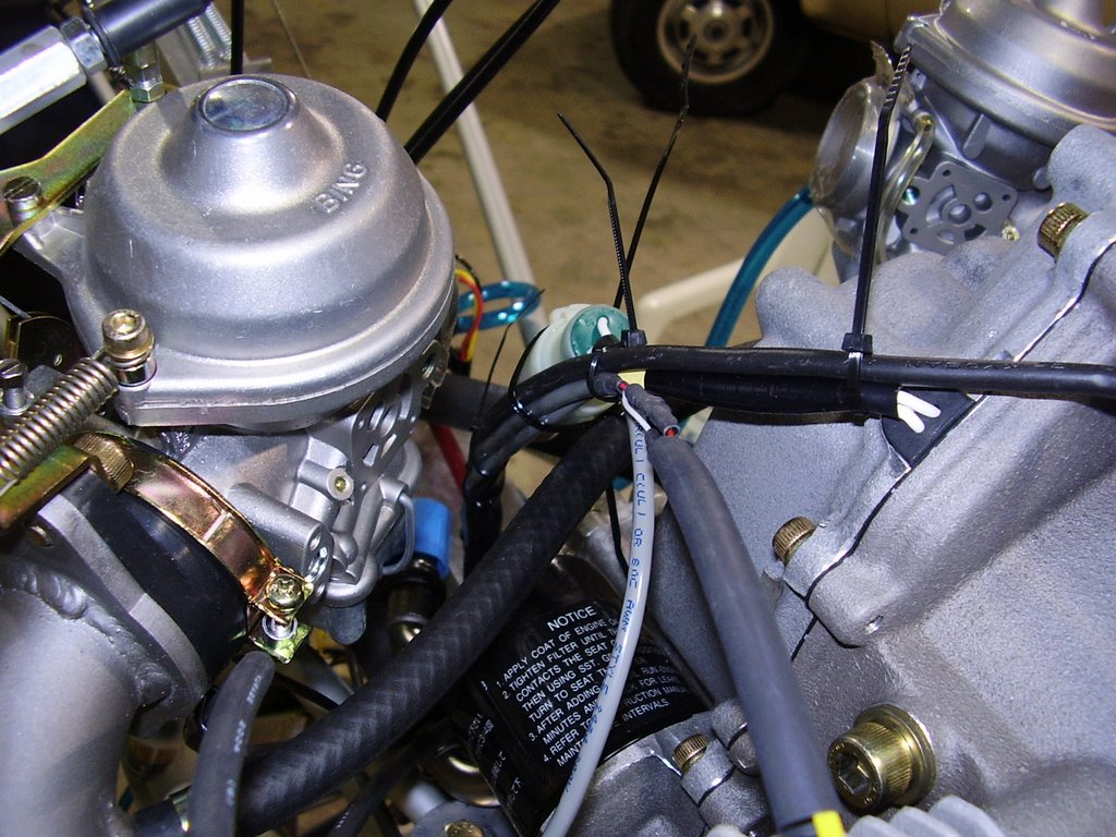
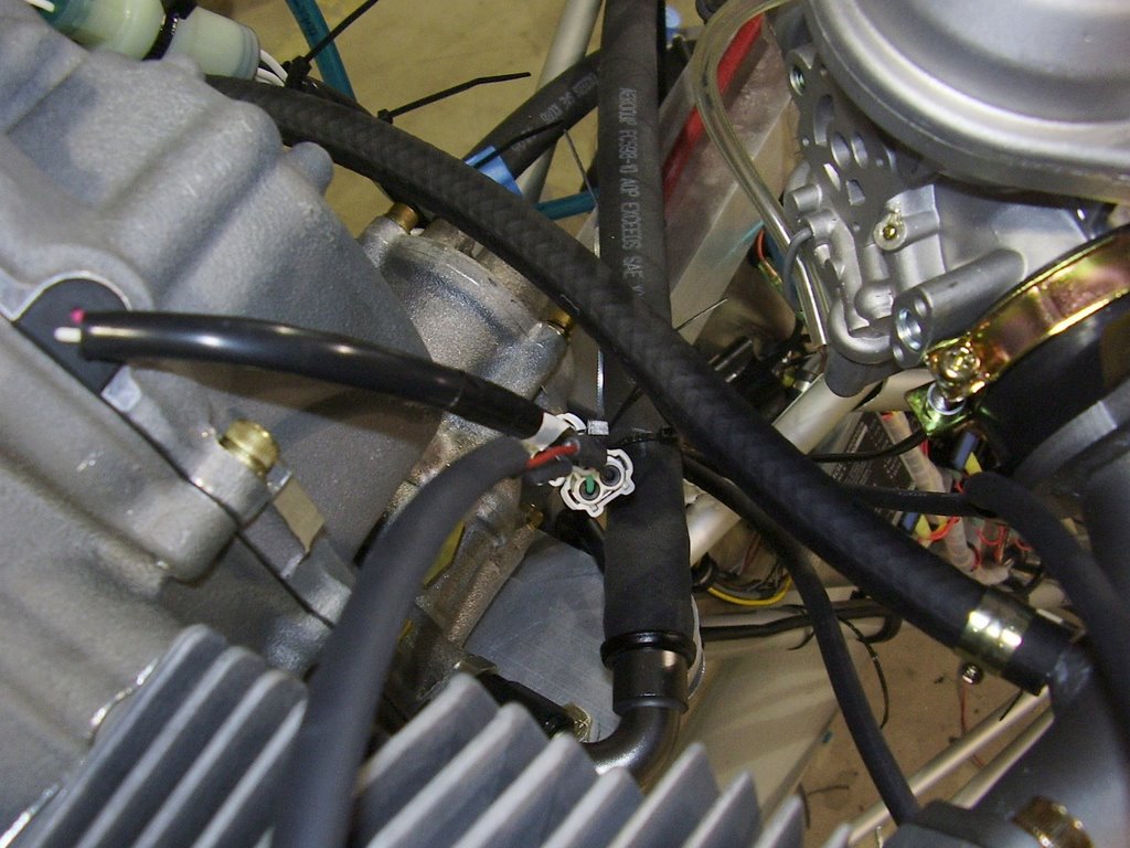
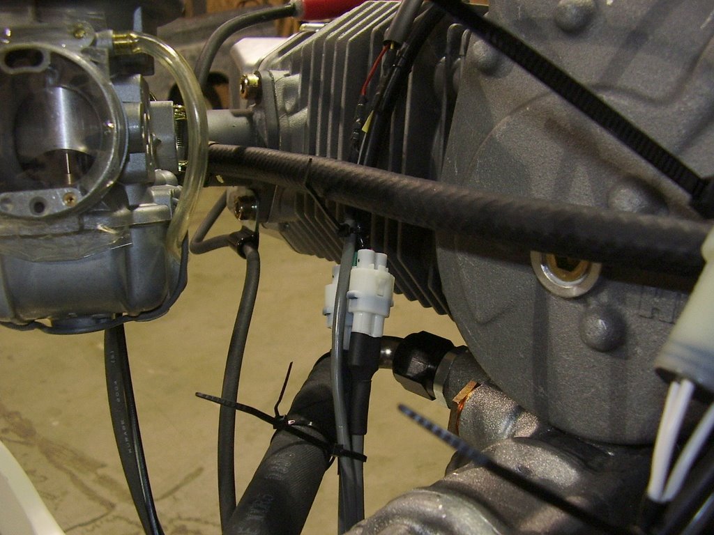
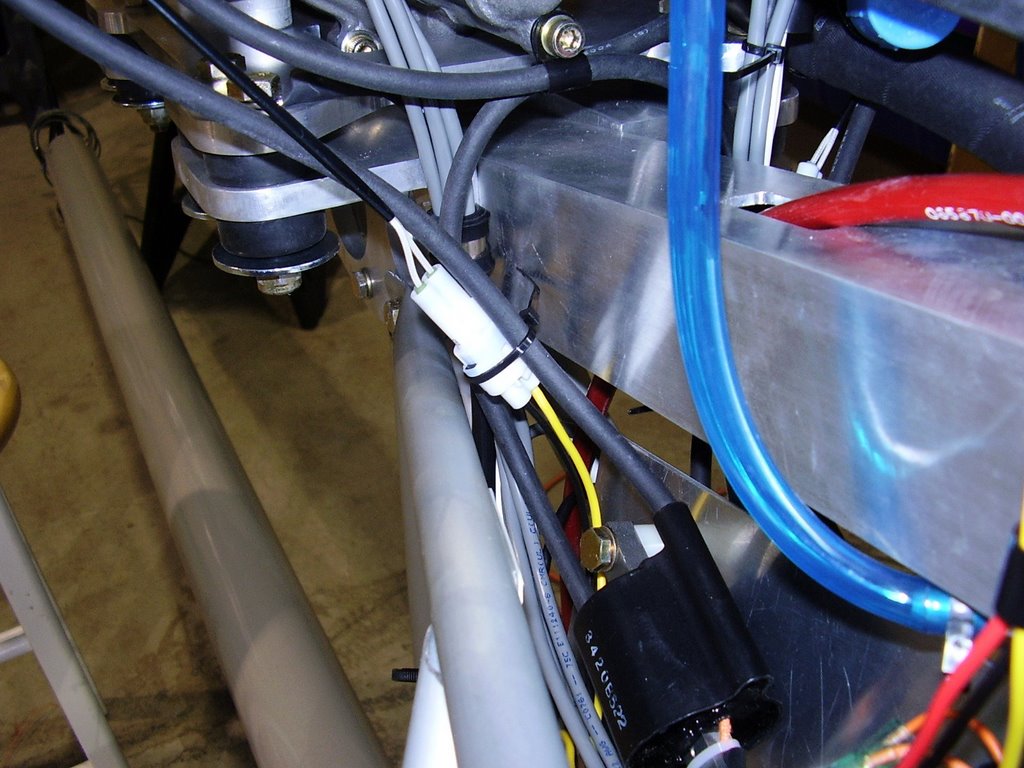
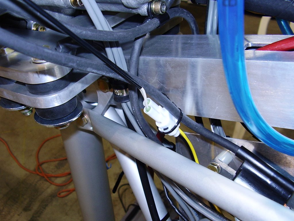
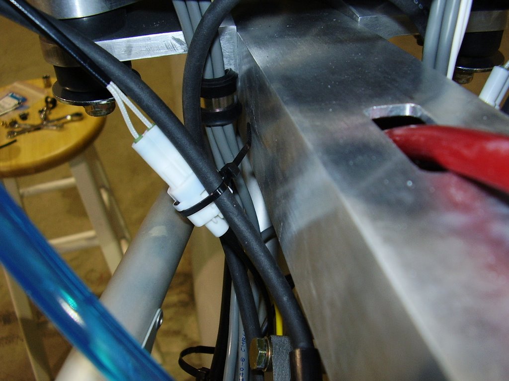
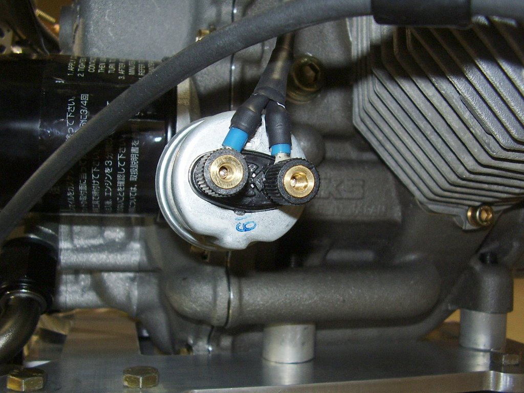
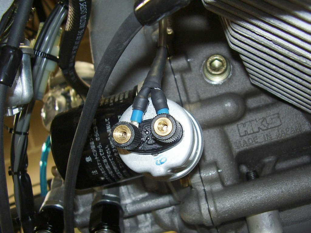
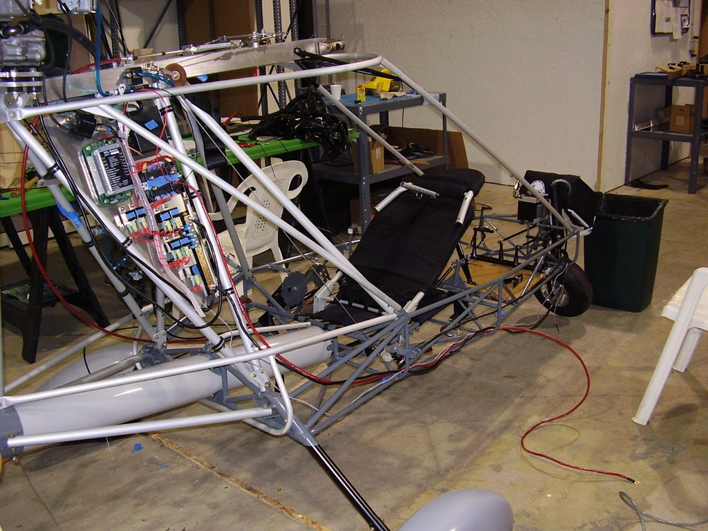
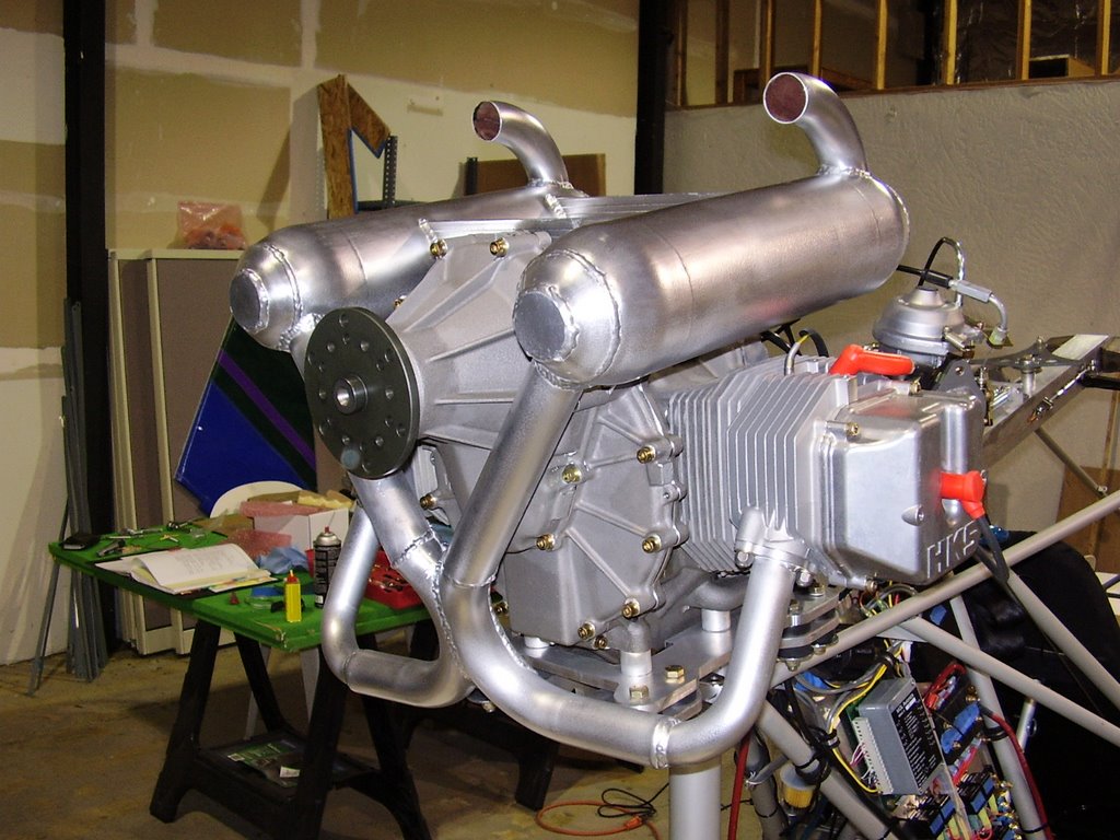
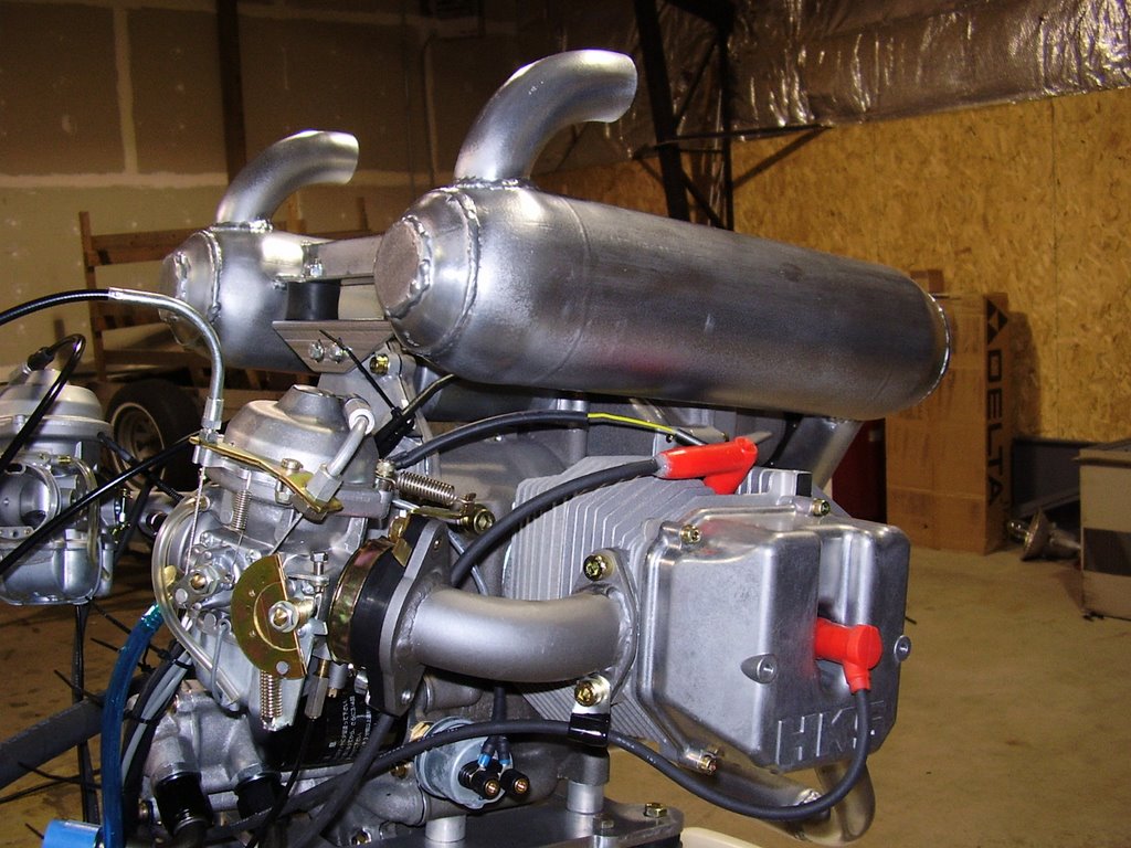
Here are some pictures of the installed exhaust.


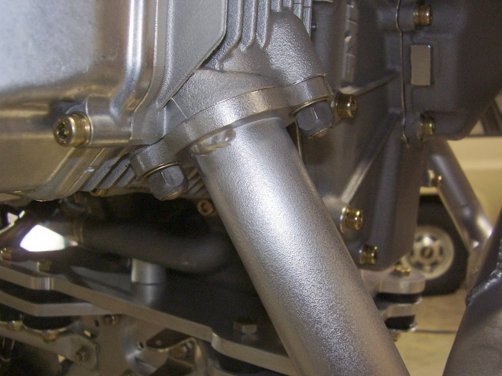
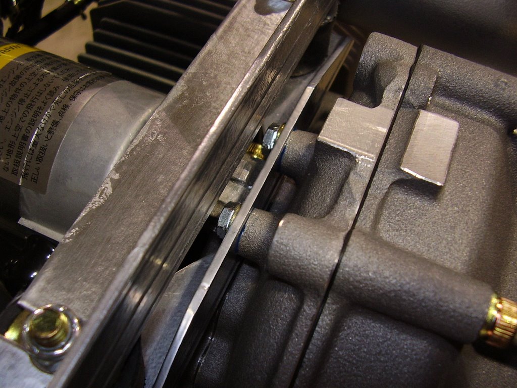
To mount the exhaust, I bolted the exhaust to the exhaust ports first. I used some AN washers and supplied gasket. The nuts seem to be self locking (triangular threads) so I didn't use any locktite. Prior to bolting it to the engine, I did drill the holes for the EGT sensors while the exhaust was on the bench.


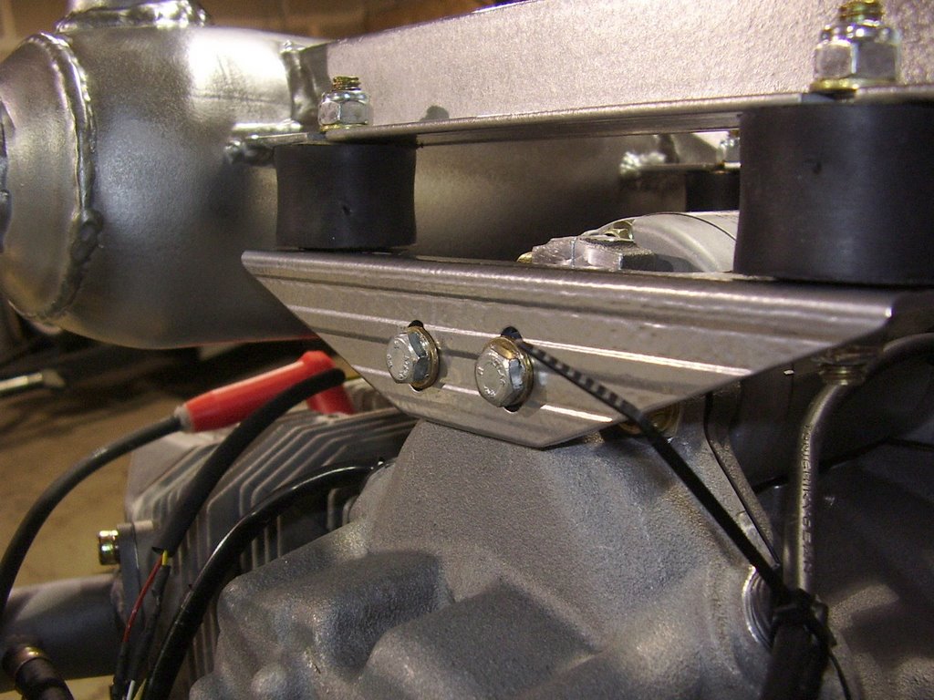
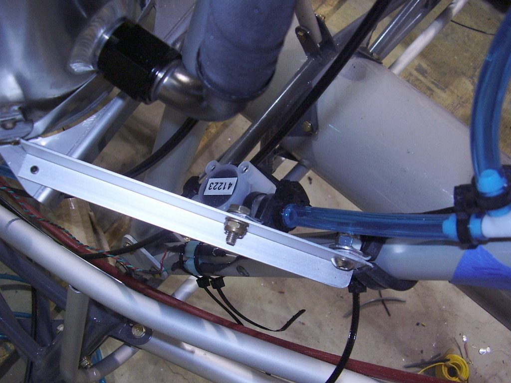
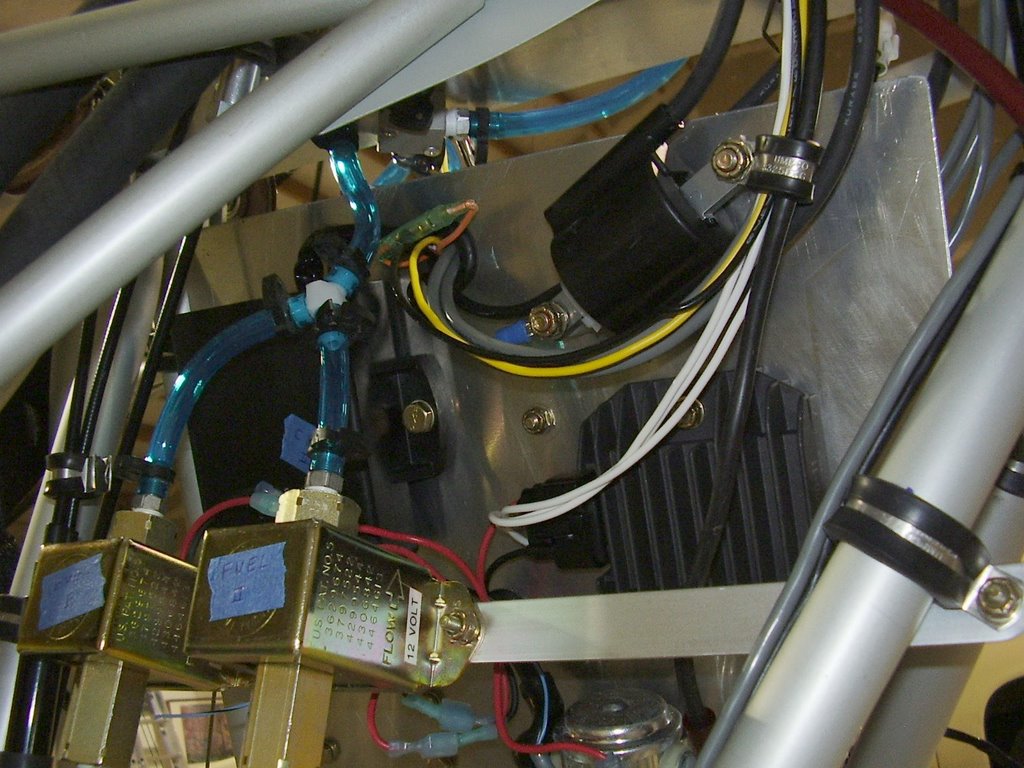
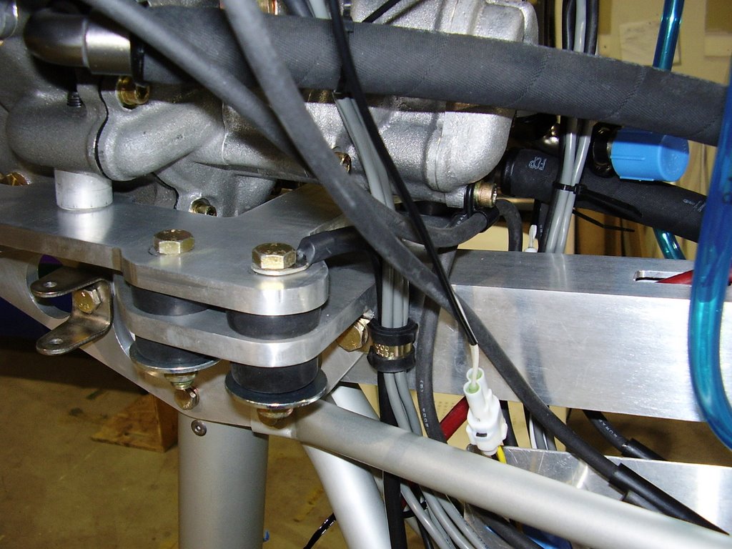
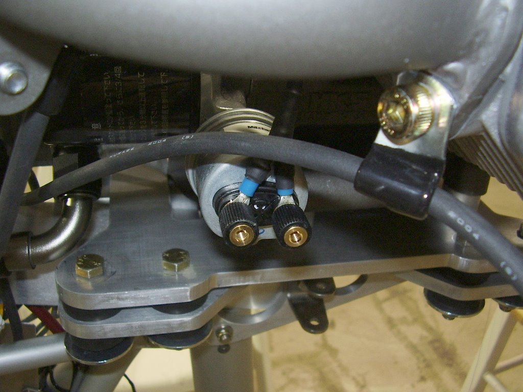
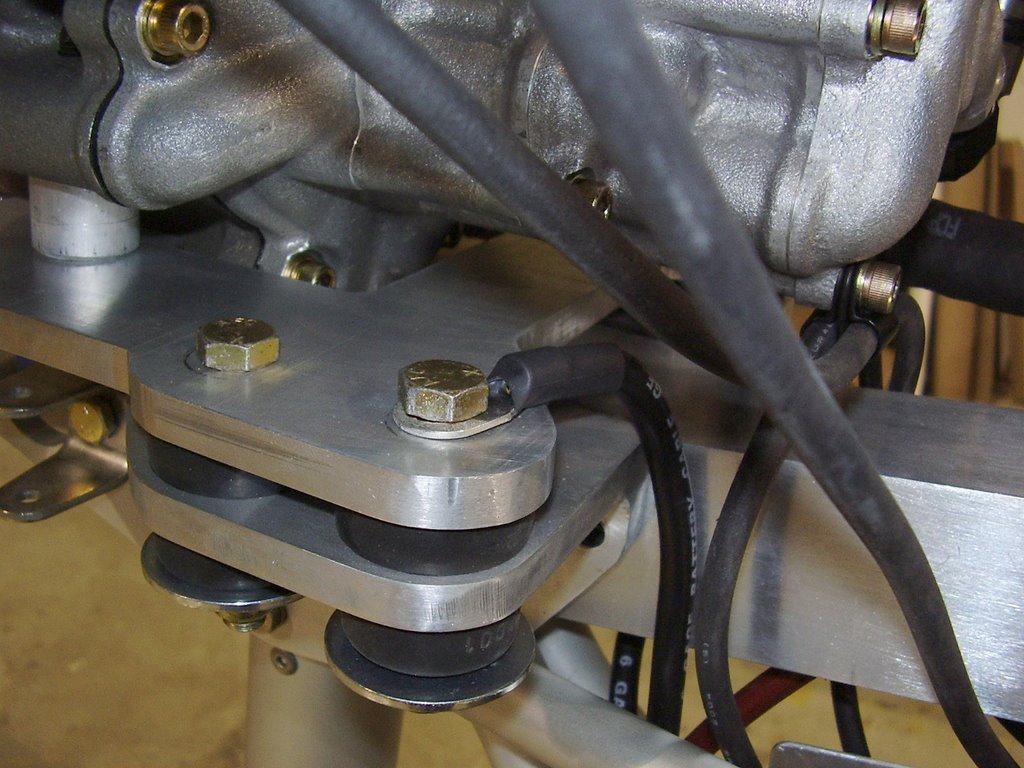
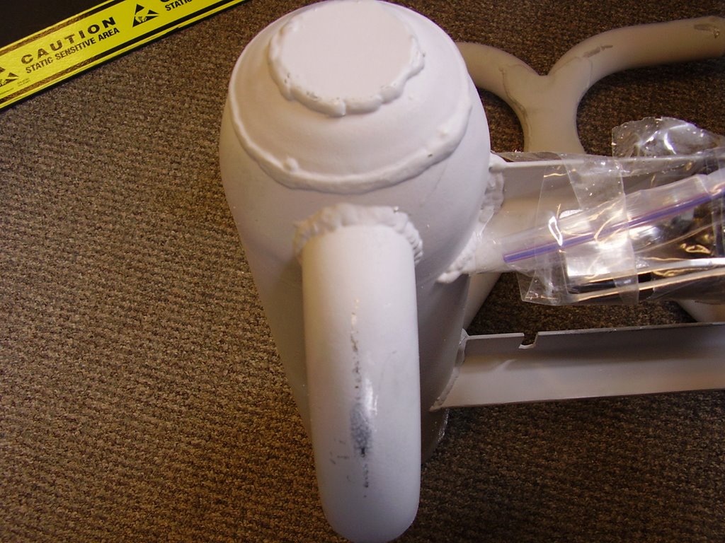
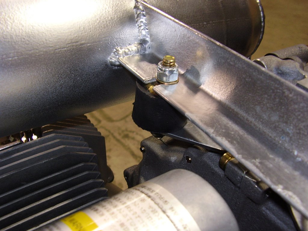
I then loosely bolted the bracket (pictured above) to the engine.


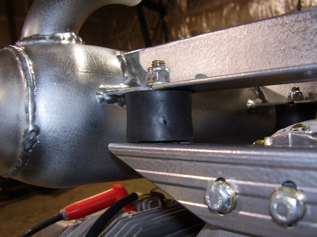
I then bolted the Lord mounts to the exhaust and bracket.


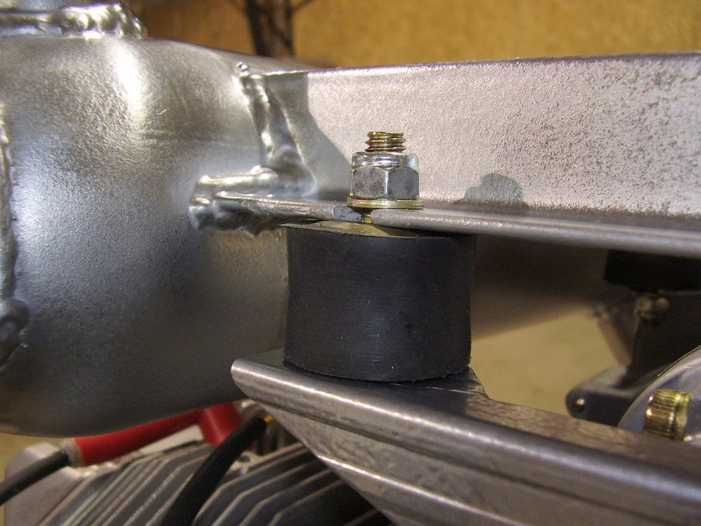
I torqued the nuts on the Lord mounts very tight. You can see the metal plate on the Lord mount popped up and against the bracket. After the Lord mounts were nice and tight, I tightened down the bolts that hold the bracket to the engine using Locktite.


I then repeated the process on the rear bracket.

Tuesday, May 23, 2006

Fuel Flow Sensor - 1 hour (275 Total)

I received some quick disconnects for my fuel lines. I intended to place them above and below my fuel filters to make them easier to replace. Unfortunately, the quick connects are too large to fit where I wanted them to.

I re-routed the fuel lines around the fuel flow sensor to alleviate the rubbing issue the fuel line was have with the oil tank bracket. I also added a wire clamp to hold the fuel flow sensor in place. The directions for the fuel flow sensor suggest that you route the sensor on it's side with a slight amount of angle. This give the internal spindle the least amount of friction since it is only resting on one bearing but allows air bubble to escape. My mounting has a little more angle than they specified but it does accommodate my fuel line routing.


Strobe Wiring - 1 hour (274 Total)

Today I routed the wire that will power my strobe. I used the same three conductor, shielded cable that I used before.

I made sure that the cable did not wrap around or interfere with the push-pull tube or trim cable within the boom tube.


The wire enters the boom tube in the same hole used for the trim cable.


I placed a rubber grommet inside one of the existing holes in the frame to prevent damage to the strobe wire and trim cable. The grommets I had were too small for this hole so I cut a couple of them up and pieced them into the hole. They seem to be snug and secure but I may need to glue them if they start falling out.


I hesitated before routing the strobe cable below the boom tube. I wanted to route it up and over the electrical panel but these seemed excessive and I did not have a wire clamp on the top edge of the panel to provide strain relief.

Monday, May 22, 2006

Engine Wiring - 12 hours (273 Total)

Over the past few days I have been wiring the electrical panel and the rest of the engine systems. Below are some pictures and some applicable notes.


Above you can see the fuel pressure sensor. I rotated the sensor by 180 degrees to keep the wiring from interfering with the fuel line. I also added a small hole to the connector to keep fluid from pooling within it.


The picture above shows a top down view of the keel tube. The bundle of wiring barely clears the keel tube and the oil fitting. I may need to add another wire clamp to keep the wires from rubbing on the oil fitting or keel tube.


In the picture above you can see the carb balance tube I replaced. I removed the existing one because it had a fitting for a pulsed fuel pump. I am using two electrical fuel pumps.


The white connectors in the center of the above picture are the timing sense lines for the engine computers. I used a three conductor, shielded cable to make extension cable for this and many other wires within the plane. I liked the cable because of it's thick outer jacket but it only uses 20 AWG stranded wire. I was concerned that the individual wires may break at the junction between the connector housing and the jacket due to vibration. To alleviate this I used several layers of heat-shrink tubing to keep the cable from flexing at these locations. I also filled the heat-shrink tubing will silicon sealant to further strengthen these joints.


The white connector in the center of this picture is the carb heat cable. This cable and the one for the second carb need to be wire-tied to one of the spark-plug wires for mechanical support. These were the only wires that I needed to route along the spark-plug wires.


In the picture above and the two that follow, you can see the wiring for the oil pressure sensor. I used silicone and heat-shrink tubing to reinforce these wires.


The picture above shows the connectors that were used for the oil temp sensor.

Sunday, May 14, 2006

Electrical Panel - 2 hours (261 Total)

Today I wired in a 15 conductor cable to the electrical panel. This cable will connect the electrical panel to the instrument pod allowing the switches in the dash to control the relays. The cable will also supply power to the instrument pod.

Since the conductors in the cable are small 20 gauge wire, I soldered the wire to the quick connects instead of crimping the wires.

I also added more plastic loom to the panel to protect the wiring. This is not shown in the picture.

Saturday, May 13, 2006

High Current Wiring - 6 hours (259 Total)

Below are some pictures of the high current wiring I implemented today. I started off with some 6 AWG wire and some copper lugs. I measured and cut the wires to length. I then soldered the copper lugs onto the wires. This was pretty easy after I got the hang of it and let the soldering iron heat up completely. I then cleaned the solder flux off and put some heat-shrink tubing over the connections.

Unfortunately, I used too much solder on one of the wires. The solder wicked up into the wire and prevented it from bending where I needed it to. Luckily this was on the short wire between the fuse panel and the starter. I replaced the wire and reused the copper lugs.


Friday, May 12, 2006

Electrical Panel - 5 hours (253 Total)

Today I replaced my cardboard mockup of an electrical panel with a sheet metal version. I was able to find some 1/16" scrap aluminum sheetmetal at the local metal recycling yard for $4. It cost me $10 to have two cuts made to it!

After removing the existing panel, I transferred the dimension for the holes over to the new panel making some slight alterations. For the items that have multiple bolts holding them in place, I drilled the holes a little larger to allow for slop in my measurements.

After cleaning up the sharp edges, I moved the electrical items over. I was able to move the majority of the items (fuse block, RDAC, Relays, and ground bar) over in one piece without having to remove all of the wiring. This saved a lot of time and hassle.