Thursday, October 19, 2006

Instrument Panel - 2 hours (431 Total)

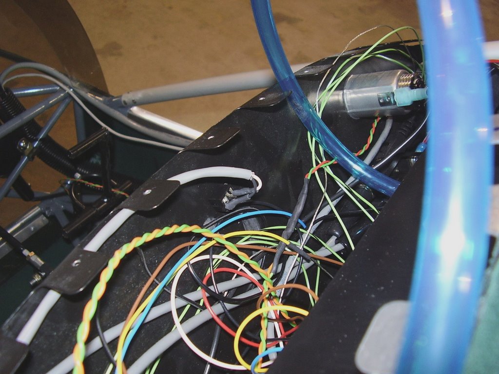
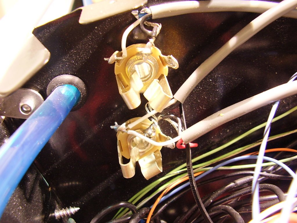
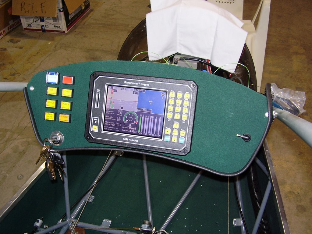
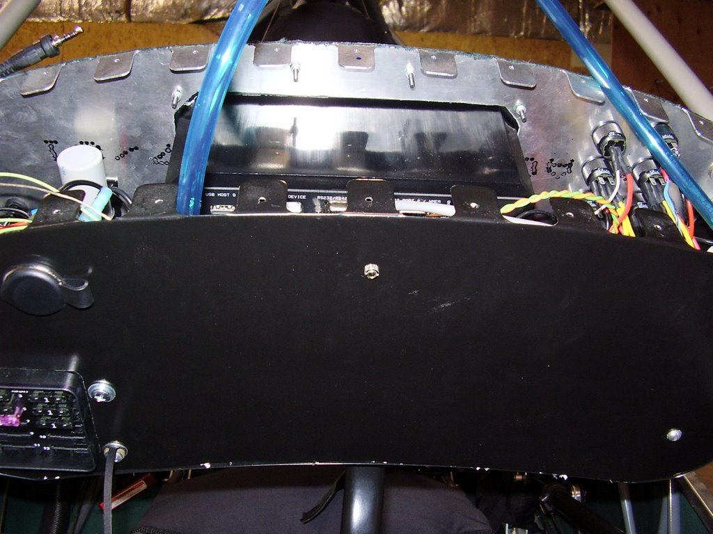
Today I finished wiring my instrument panel. The last bit of wiring I needed to do was add a stereo jack for the push to talk (PTT) cable and button I will install later. I bought a coiled cable similar to a telephone hand set cable but with 2.5mm stereo connectors. I installed a stereo jack in the back side of the panel. You can see the jack and wiring in the three following photos.


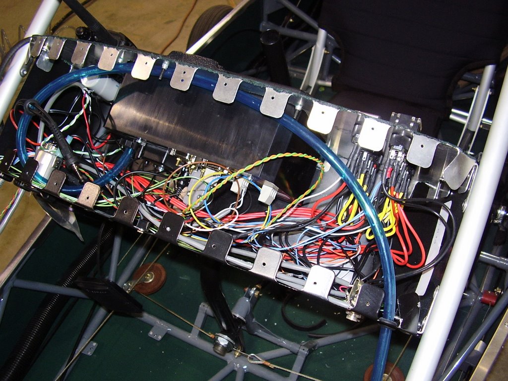
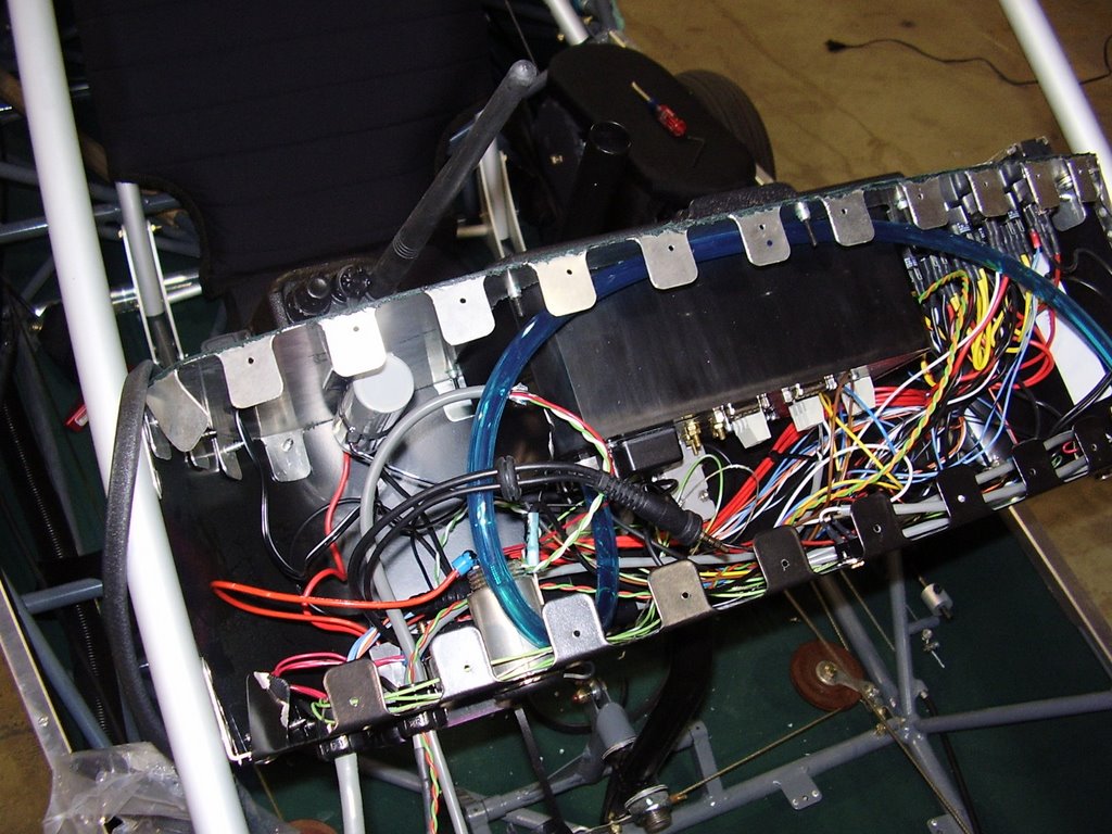
Below are two photos of the completed wiring... What a mess! I considered using wire ties to secure some of the wires and neaten thing up but I figured that would only cause me problems if I needed to do any future work or repairs on the wiring. One thing that I did do was coat the hot end of the cigarette lighter plug with some liquid electrical tape. This will hopefully prevent it from shorting out to the non-shielded ground wires.


Wednesday, October 18, 2006

Enigma is here! - 3 hours (429 Total)

My Enigma finally arrived. The Enigma is the color upgrade to my Stratomaster instrument display. Other than having a color display, the other neat feature is the built in GPS.

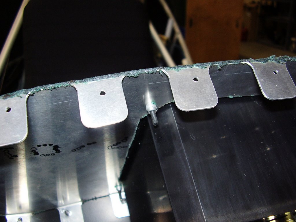
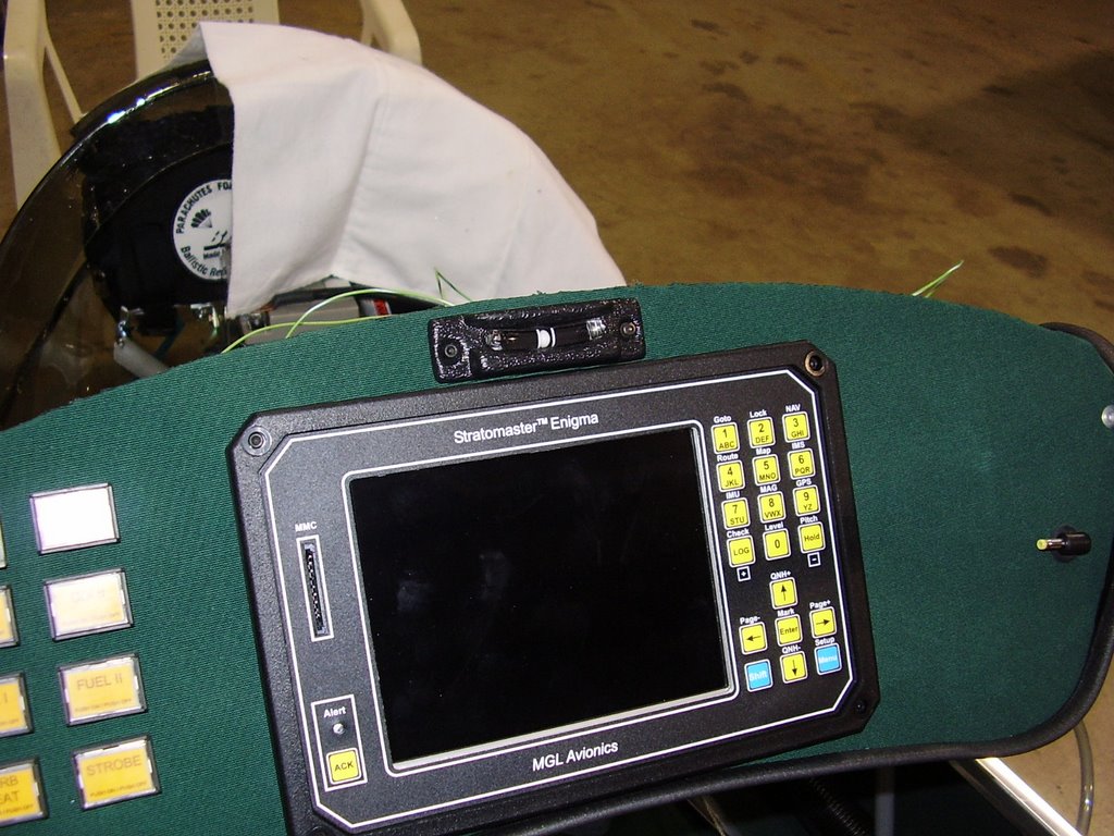
Below is a photo of my installed Enigma. The second photo shows the rivnuts I used to mount the Enigma.


Below is a photo of my slip indicator. I mounted it with the rivnuts also.


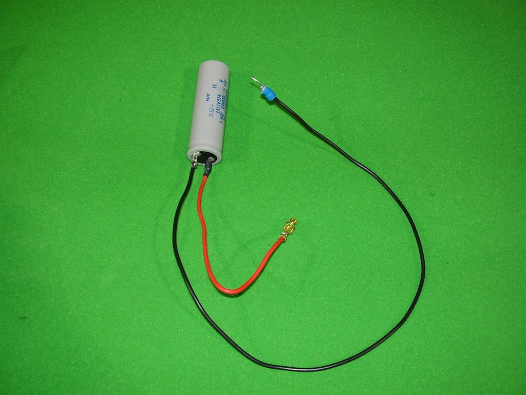
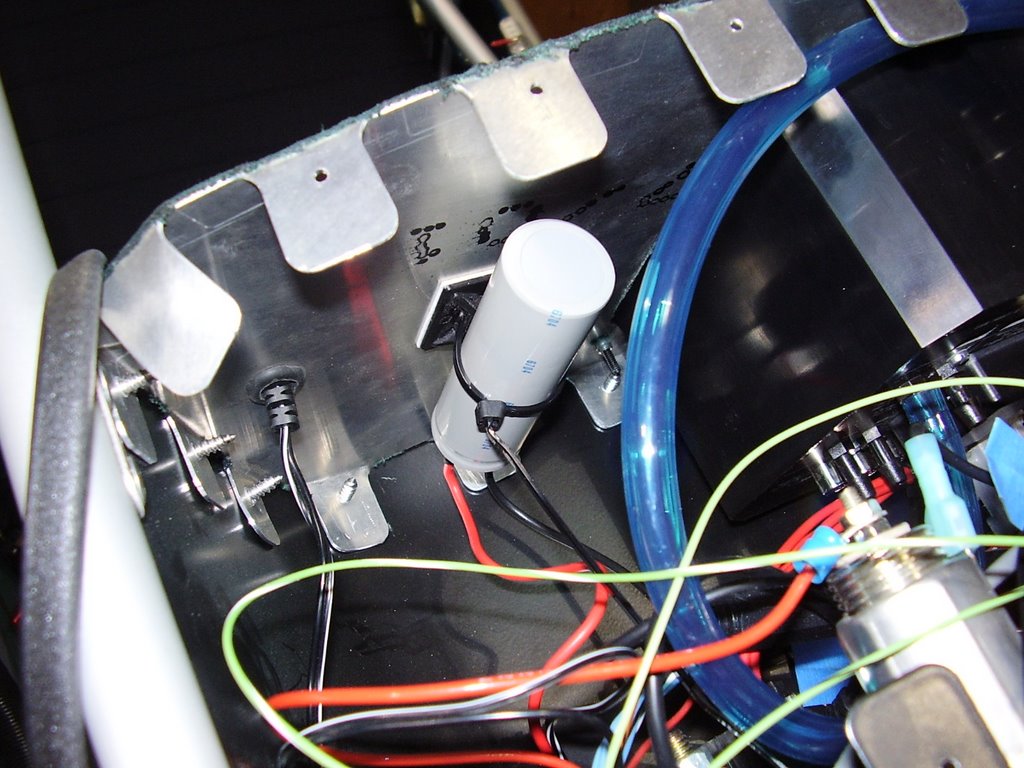
My Stratomaster suffered from resets occasionally when I attempt to start my engine. The starter would suck so much current that the voltage would drop to levels below what the Stratomaster required to operate. I installed the 3000uF, 30V capacitor into my instrument pod to try to alleviate this problem. I chose this cap because of the large solder lugs it has.

The cap seemed to help some but I still got some resets when I continued to crank the engine to the point where the battery drained down and was having difficulty turning the engine over. The resets would be expected at this point since the starter is drawing a huge amount of current when stuck.


Wednesday, October 11, 2006

Electrical Panel Changes - 1 hour (426 Total)

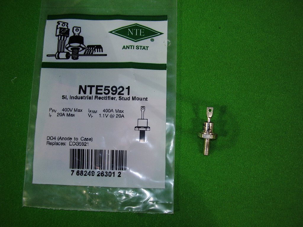
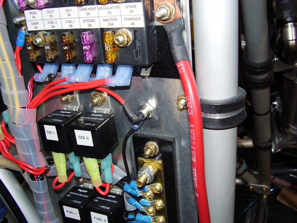
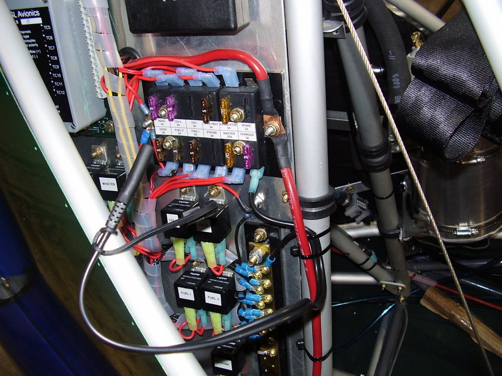
The instructions for the strobe that I installed recommend a diode to be installed to protect the electrical system from negative voltage spikes. Below are some pictures of the diode I installed.


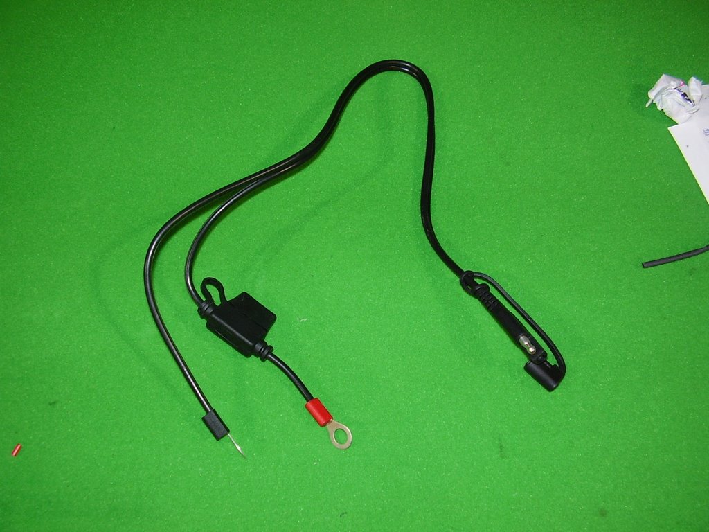
I also purchased a battery charger/tender. The unit came with a cable designed to be wired into your electrical system for easy connecting to the charger. The cable came with a built in fuse holder which I cut off. I wired the cable in to one of my empty fuses; see the pictures below.


Nose Wheel - 1 hours (425 Total)

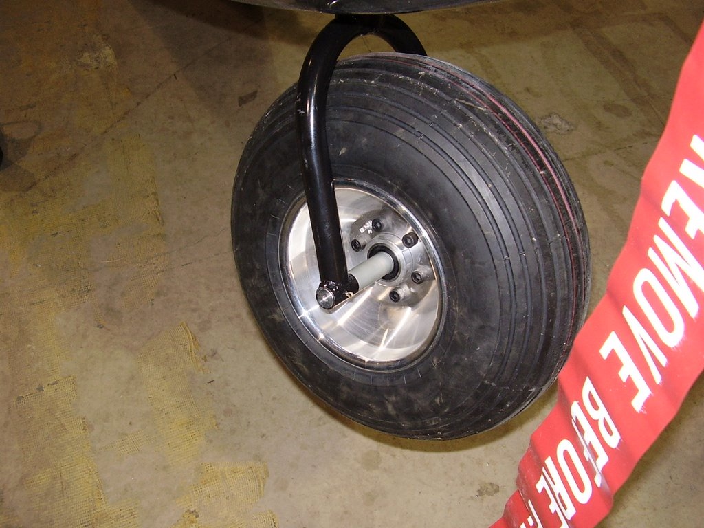
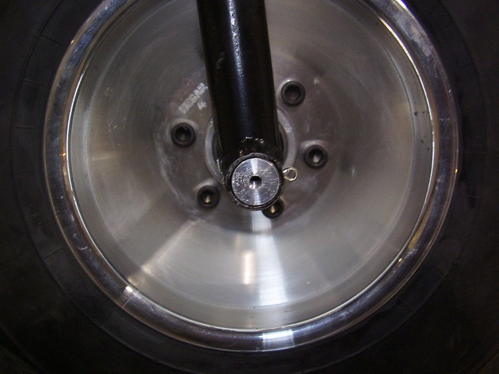
Today I drilled and installed the cotter pins that hold the nose wheel axle in place. This would have been a pretty easy and quick task if I hadn't has broken off my drill bit in one of the holes.


Tuesday, October 10, 2006

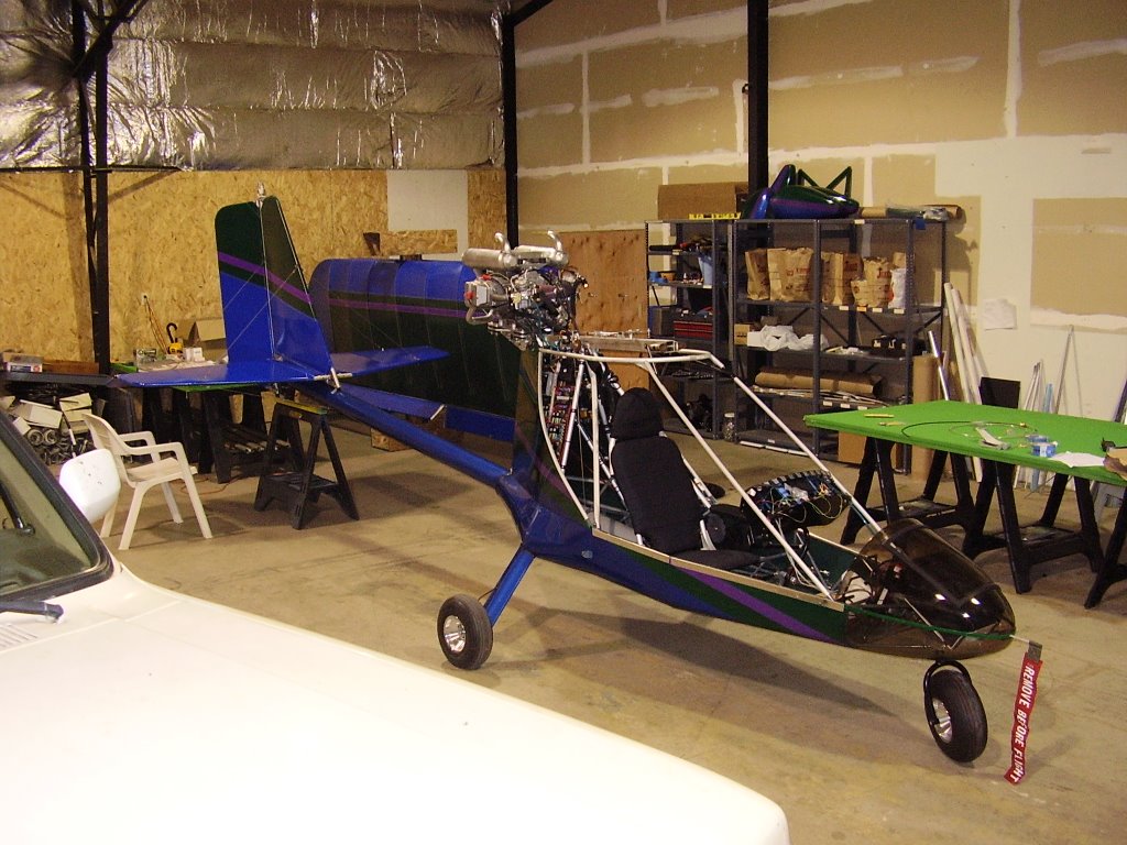
Pretty Picture... - 0 hours (424 Total)

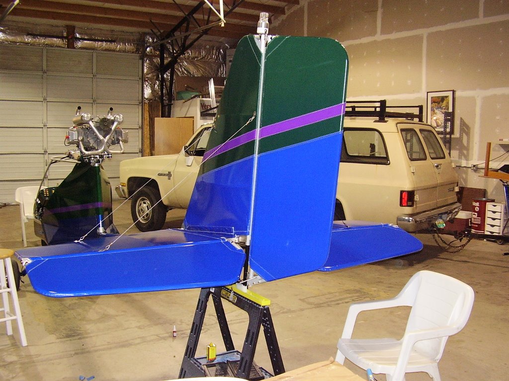
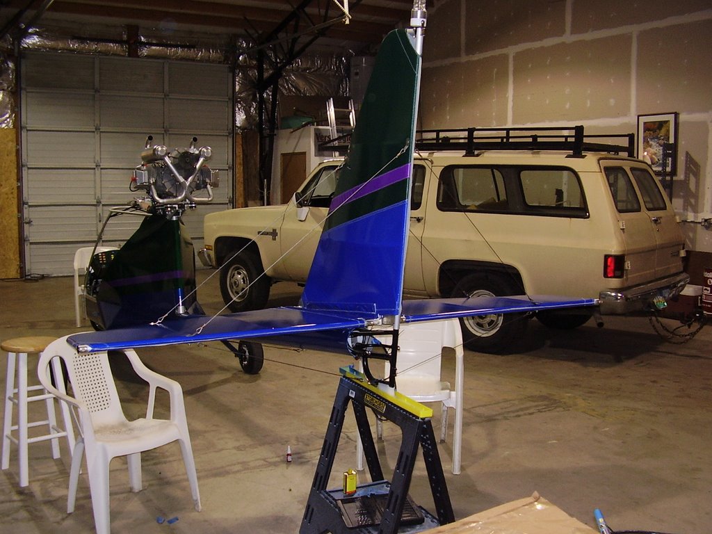
All too often I forget to take a pictures that show the entire plane. Here is one that shows my progres.

Sunday, October 08, 2006

Arm Rest - 1 hour (424 Total)

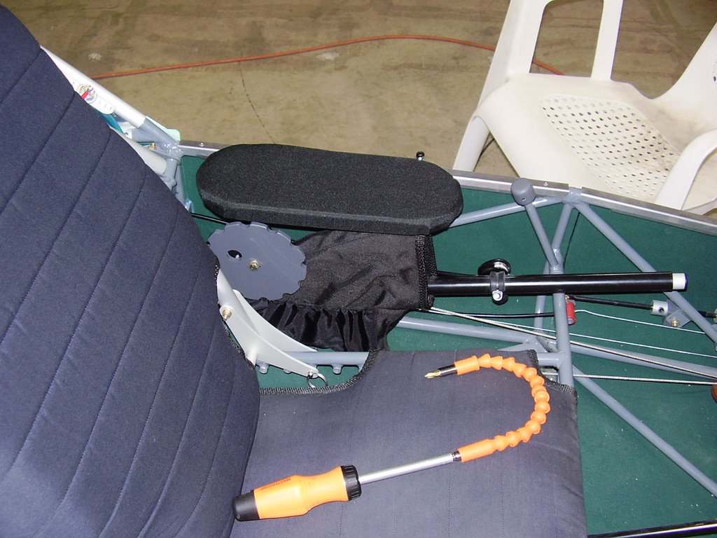
The last thing I did today was build and install my arm rest. Rans provided a pre-shaped piece of plywood, a rough cut piece of foam, and an oversized piece of fabric. I cut the foam to match the shape of the plywood and stapled the fabric over the top.

The hard part was screwing the completed arm rest to the plane. In the picture below you can see the flexible shaft screwdriver I used to screw the arm rest into place.

Elevator Trim - 5 hours (423 Total)

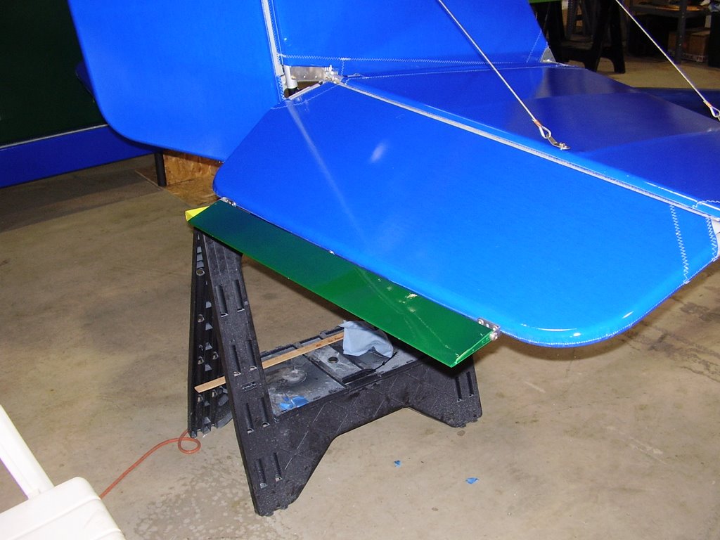
Today I installed the elevator trim tab.

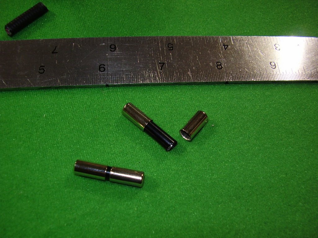
The hinges for the trim tab went together pretty easily. They use an aluminum tube cut to 1/16" long as a bushing to reduce the friction in the hinge. There is still a significant amount of friction but the tab does move. If this doesn't loosen up over time I may need to replace the 1/16" bushings with slightly larger ones.
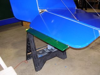


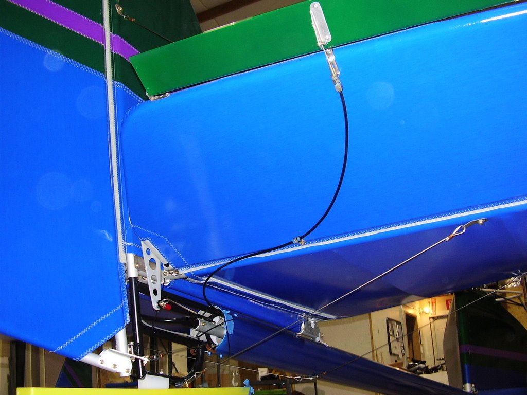
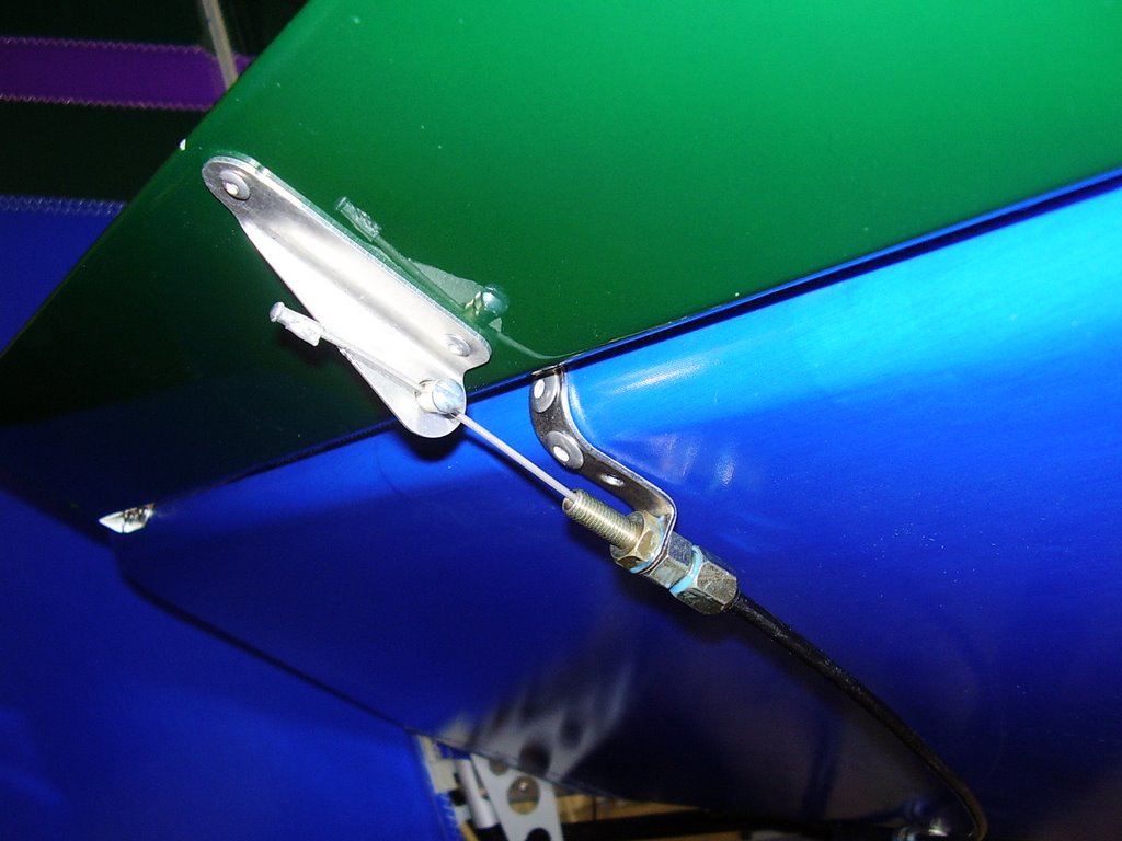
The actuator cable for the trim is routed out the tailboom, through a cable clamp, to a stopper that is riveted to the trailing edge of the elevator.

The cable clamp is attached to the leading edge of the elevator with a bolt and a rivnut. I purchased a tool specifically designed to install rivnuts. Unfortunately, it worked too easily. I over tightened the rivnut and stripped out the threads. I needed to drill out the rivnut and install a second one. The manual only calls for one rivnut and cable clamp but the kit came with two. Rans may have intended for the second one to be used on the trailing edge of the horizontal stabilizer to prevent the cable from rubbing on the fabric.
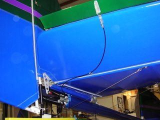


To cut the cable and housing to the proper length, I needed to unbolted the trim wheel from the flap lever mechanism. This allowed me to disassemble the trim wheel and pull the cable out of the housing. Otherwise, there wouldn't have been a way for me to cut the housing shorter than the cable.

I cut the cable so that I have an inch or so of extra length in case I need to make any adjustments. I set the trim tab to be in line with the elevator while the trim wheel was centered. I crimped a cap onto the end of the cable to keep the sharp cable end away from my skin.
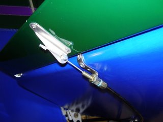
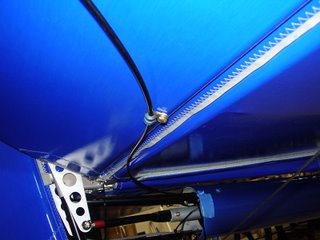


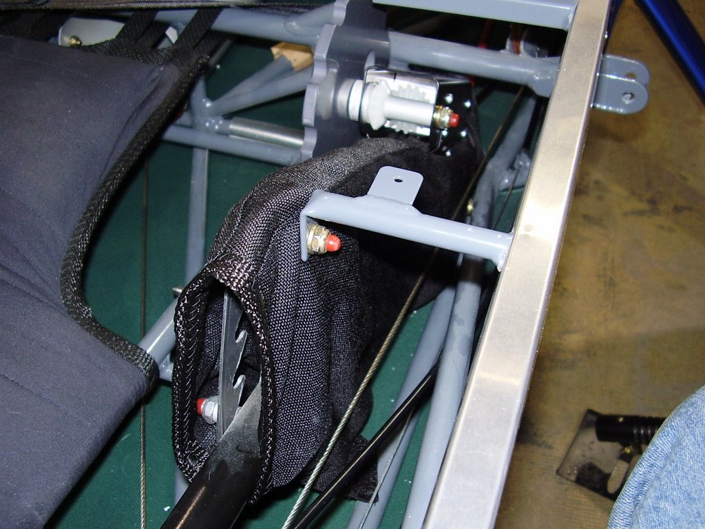
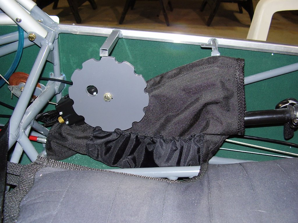
Since I had to remove the trim wheel from the flap lever mechanism, I went ahead and installed the fabric covering over the flap lever mechanism. I needed to cut the fabric with my soldering iron so it would fit over the trim wheel bracket.
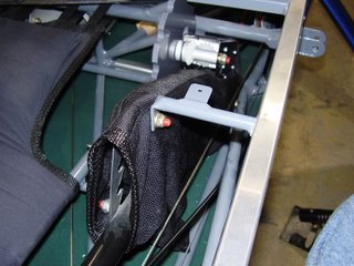


I used Locktite to secure all the bolts and screws.
Saturday, October 07, 2006

Elevators - 2 hours (418 Total)

After I finished with the rudder, I installed the elevators.
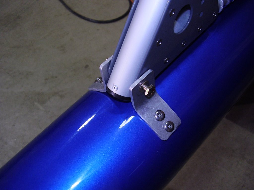
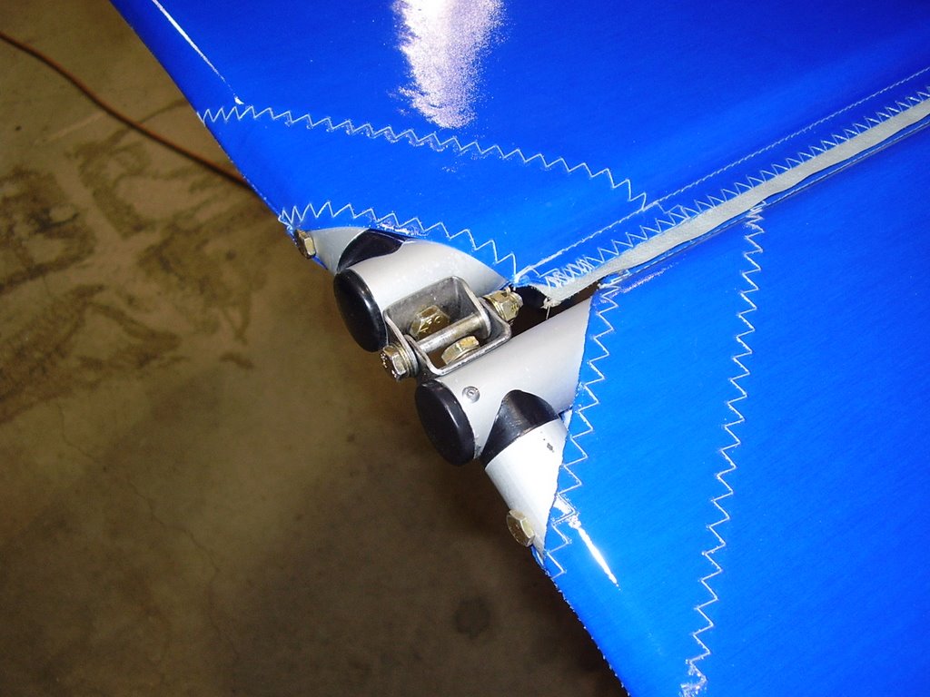
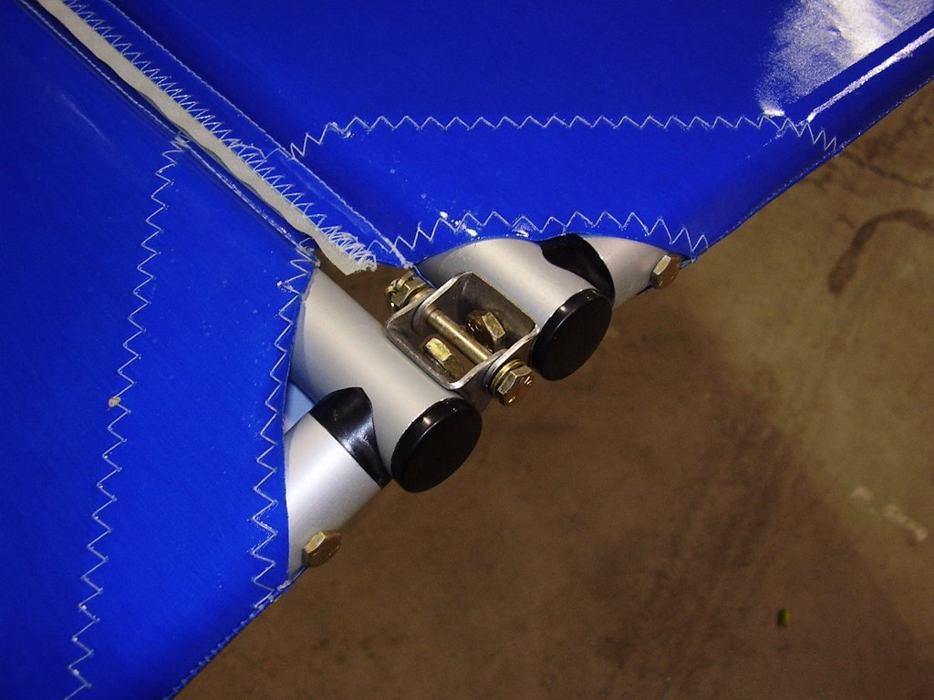
These went on without much difficulty. Each elevator has two hinges and a elevator horn for actuation. I needed to rotate one of the elevator horns because I had installed it backwards.


Once I installed the hinge and horn bolts, I installed the necessary lock rings and cotter pins. I also lubricated the hinges with a spray on teflon lubricant.


I also installed the black plastic caps on the outside ends of the elevator's aluminum tubes. The assembly manual calls for the caps on the inside ends of the tubes but I didn't see the need.


Rudder - 3 hours (416 Total)

Once the stabilizers were in place, I installed my rudder.

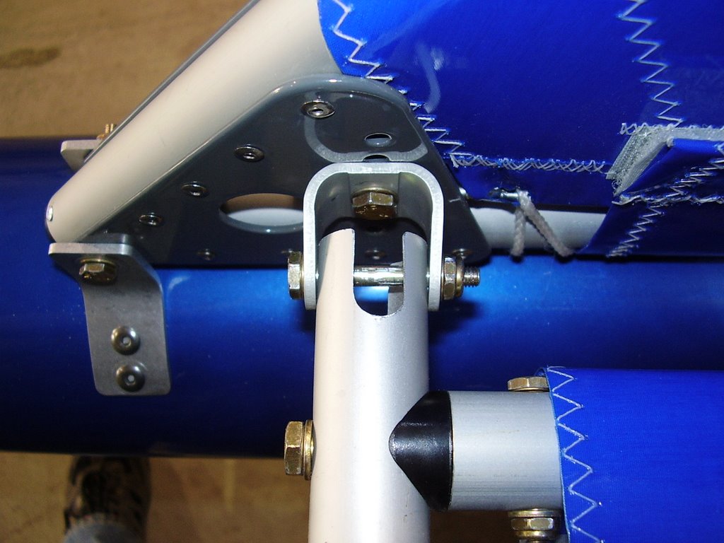
The rudder has two hinges that connect it to the tail. One hinge bracket is bolted to the top of the aluminum tube of the vertical stabilizer and the other is welded to the tailboom extension. The distance between the hinges will vary depending on how far down the vertical stabilizer is placed on the tailboom extension. I should have checked the hinge spacing prior to drilling the hole in the tailboom extension to ensure the rudder would match up but I didn't think of it at the time. Luckily, the rudder hinges mated up without any problem.

Once the hinge bolts were installed, I connected the rudder control cables. I needed to change the connection point of the cables where they connect to the rudder pedals to allow for the proper length. I did not put too much effort into tensioning the cables; I only made sure the majority of the slack was eliminated.


After testing the movement of the rudder system, I installed cotter pins in to the pulleys and hinge bolts. I also sprayed all of the moving parts, except the pulleys, with a teflon lubricant.


Stabilizers - 4 hours (413 Total)

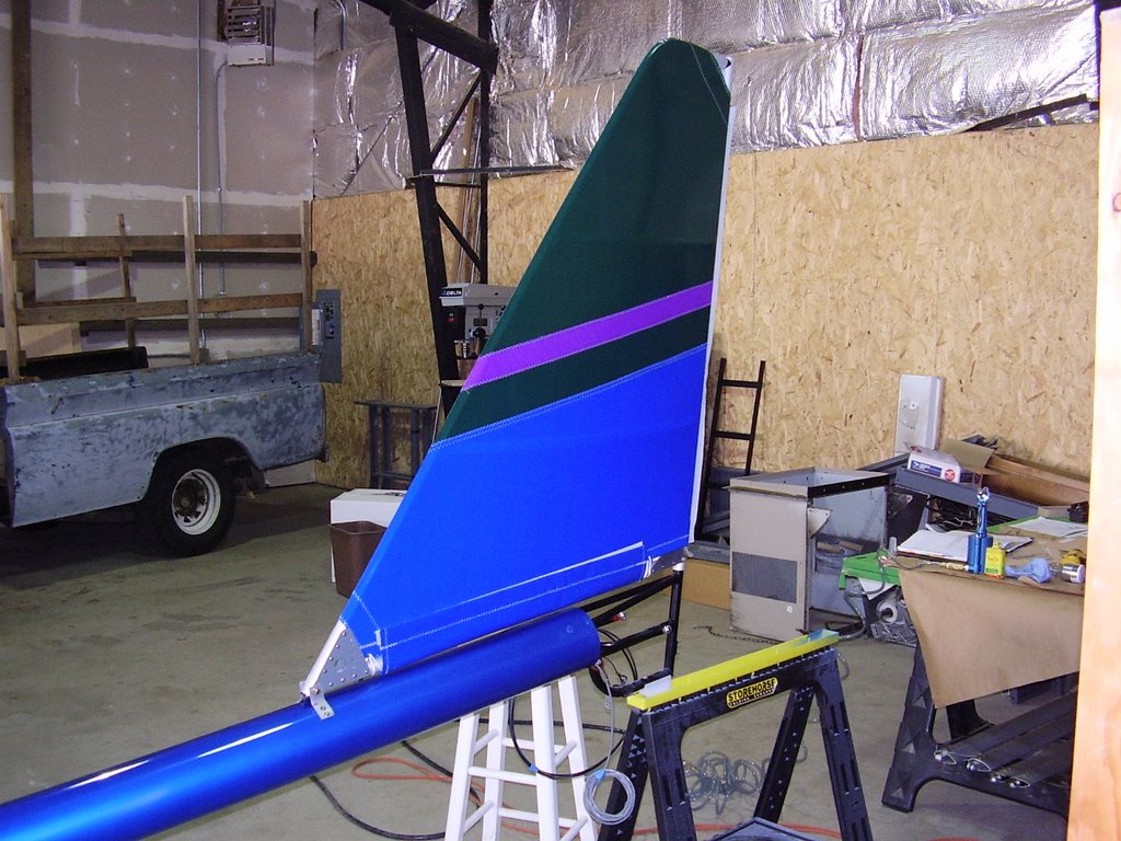
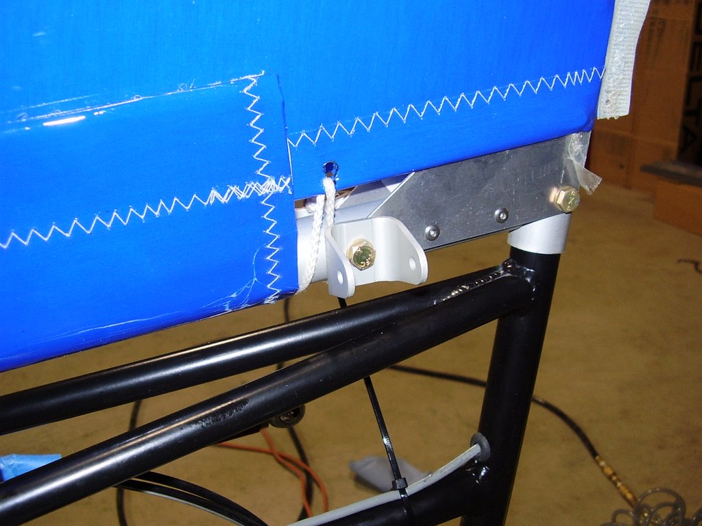
During the strobe installation, I also installed the vertical stabilizer.

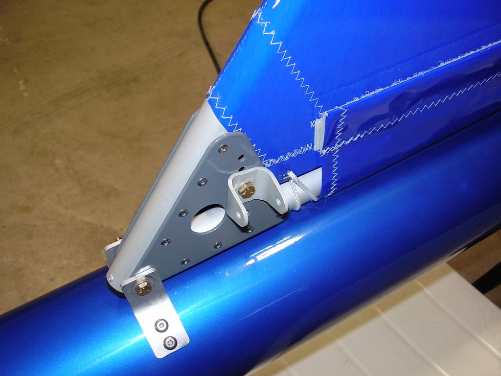
The vertical stabilizer mounts to the plane with two bolts. One bolt goes through the tail boom extension. The other goes through a set of brackets that are riveted to the tailboom.


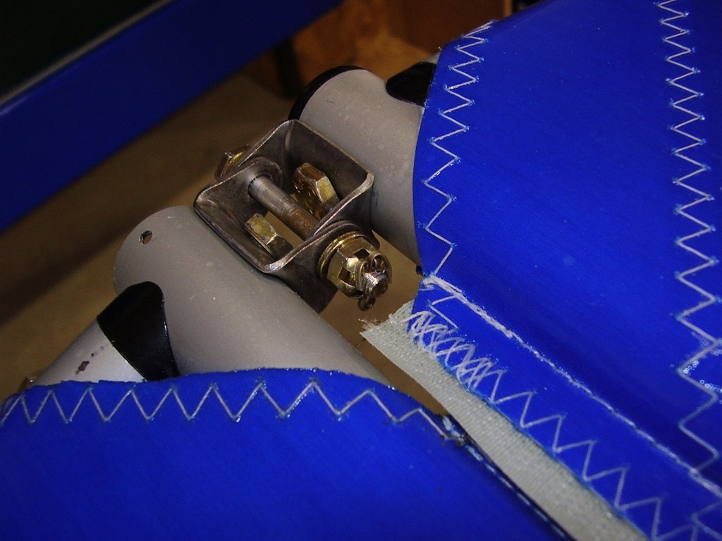
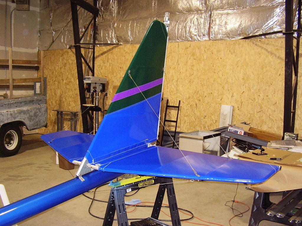
I then attached the horizontal stabilizers. The base (root) of the horizontal stabilizers bolt onto the vertical stabilizer with U-brackets. Then eight cables are used to hold the stabilizers in position.

The cables need to be secured very tightly to prevent them from vibrating in flight. The tangs on the cable ends have four holes in them to fine tune their tension/length. I was able to make the cables very tight by installing all of the cables with only finger tightened bolts. Once all the cables were installed, I removed their slack by tightening all of the bolts.


The assembly manual calls for only one thick washer to be used on the bolts and U-brackets. I used two thin washers on each side instead.
Strobe - 1 hour (409 Total)

Today I was able to accomplish quite a bit. The first thing I did was install my strobe light.

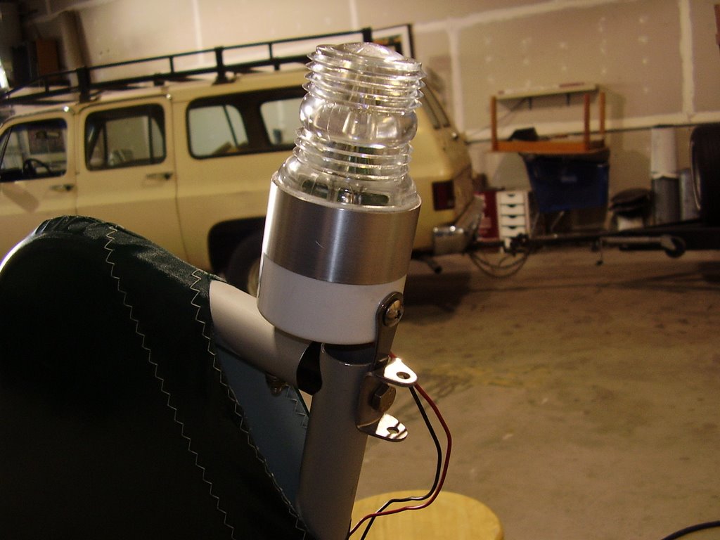
I purchased a SC103 ultralight strobe light with the intent of mounting it onto my tail. I am not required to have a strobe light on the plane but it did seemed like a good idea for the sake of visibility and safety.

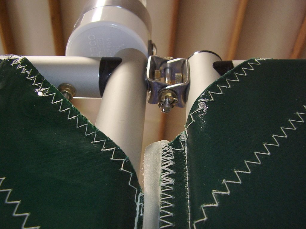
The strobe light came with a metal tab attached for mounting. This turned out to be quite convenient for mounting on the top of my vertical stabilizer. I used a bench vise to bend the tab into a slight curve to better fit between the aluminum tube and curved hinge I mounted it between.

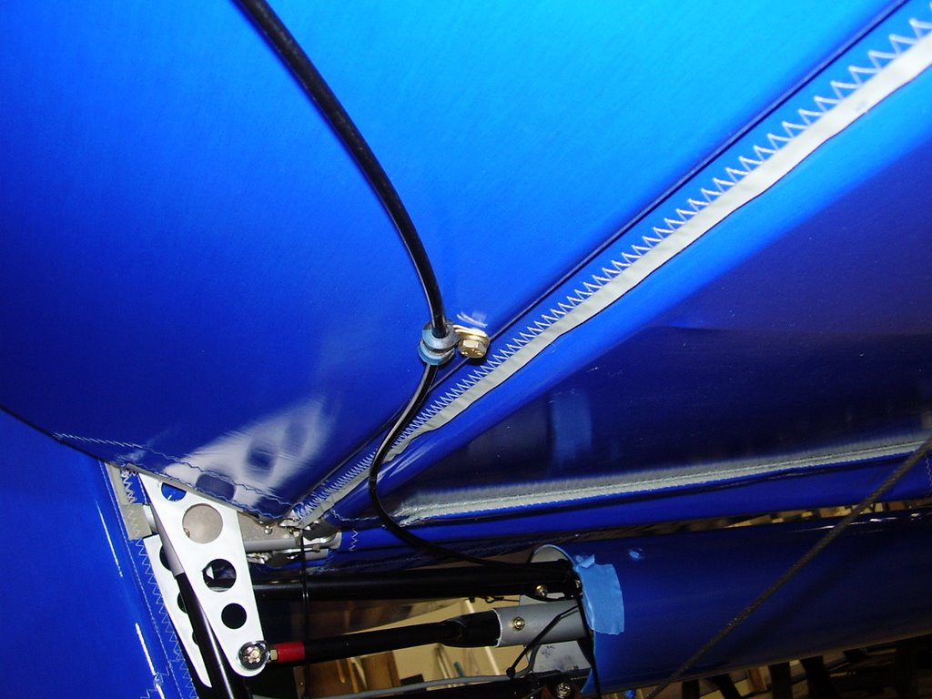
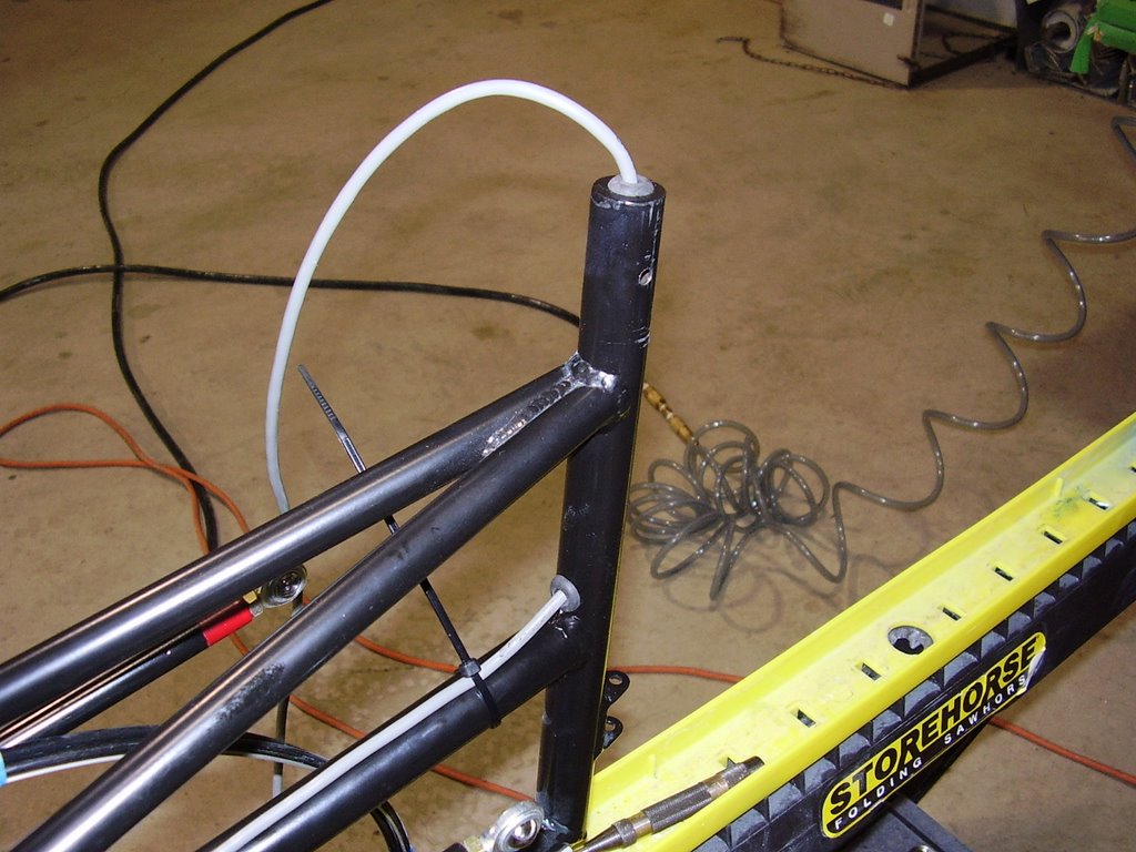
I ran the wiring down through the aluminum tubing of the vertical stabilizer. I needed to drill two holes in the tailboom extension to allow for the wiring. I used rubber grommets to protect the wiring from the sharp metal edges. I then used zipties to secure the wiring to the tailboom extension to ensure that it would not interfere with the rudder cables or elevator push-pull tube.
I soldered the pigtail leads from the strobe directly to the jacketed wiring that I routed through the tail boom. There is about a foot worth of slack in the wire that was stuffed down the top of the aluminum tube of the vertical stabilizer in case the strobe needs to be replaced or serviced.


Thursday, October 05, 2006

Brakes - 2 hours (408 Total)

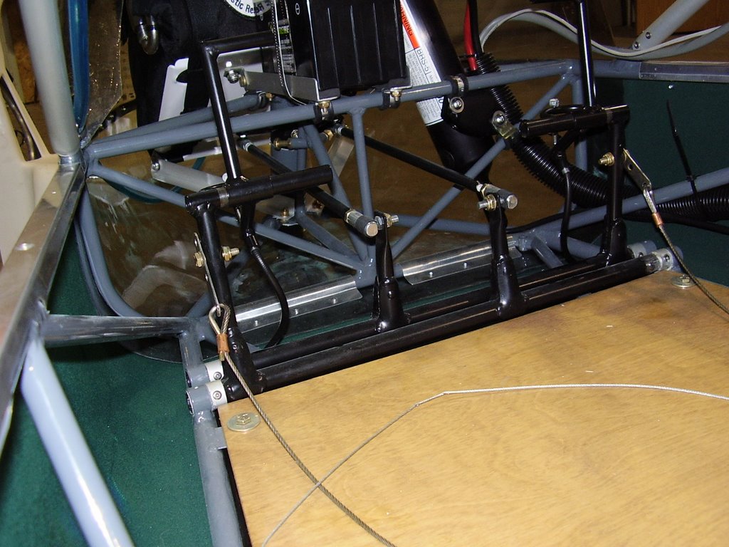
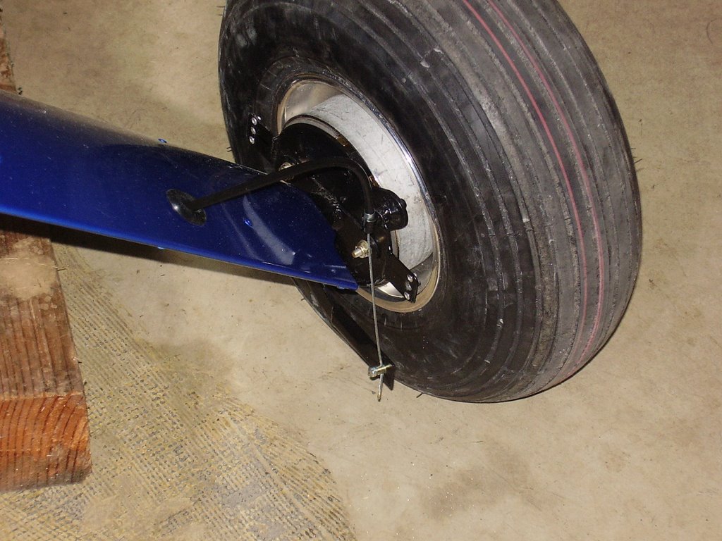
Today I routed the cables for my brakes.

Several months ago I temporarily routed the brake cable for just the left brake to test it's functionality. If they didn't work well enough, I was going to replace them with hydraulic brakes. The cable brakes seam to function adequately. I do wish they had a parking brake feature but I will see if I can live without it.

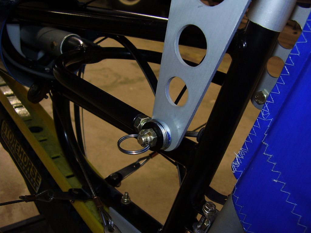
One of the things I don't like about the brake setup is that the pedals stick out by several inches. This means that I would have to press (actuate) the brakes to rest my feet on the rudder pedals. This was not comfortable for me so I created a standoff (see the first picture) out of a short piece of cable housing. This standoff allows my feet to sit flush against the rudder and brake pedals. This does reduce the range of motion of the brake pedals but I should still have enough to fully actuate the brakes.


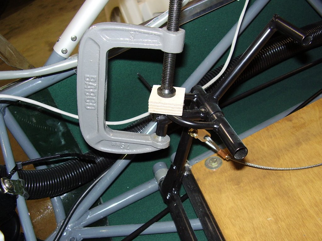
Some of the holes provided for the cable housing and caps had too much paint in them. In the picture below you can see how I "encouraged" the cap to fit into place.


I trimmed the brake cables to length and used a soldering iron to keep the cables from fraying. The brake cables were adjusted so that there is a slight amount of drag on the brake drums. This dragging only occurs in some spots as the wheels are rotated. I expect this to go away after the cables stretch and the brake pads become warn.