Saturday, May 13, 2006

High Current Wiring - 6 hours (259 Total)

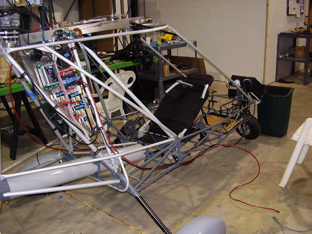
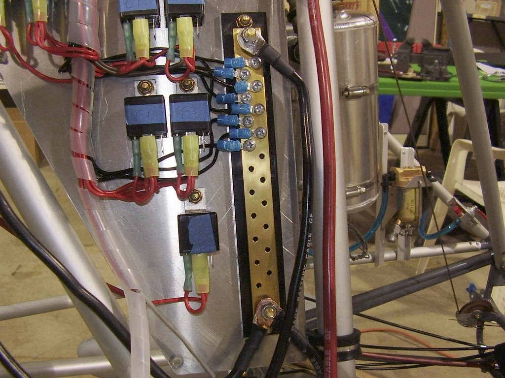
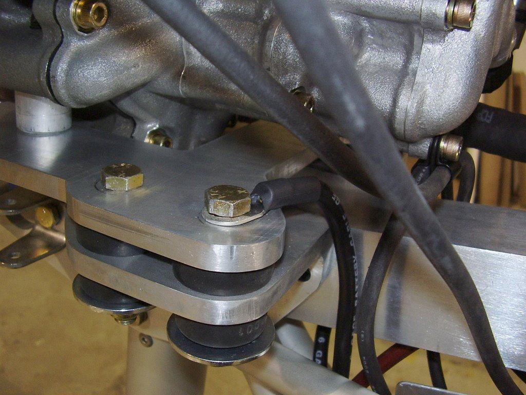
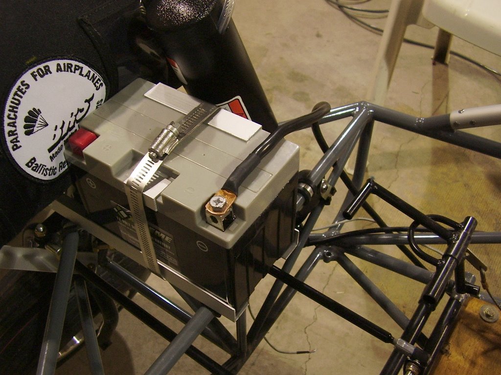
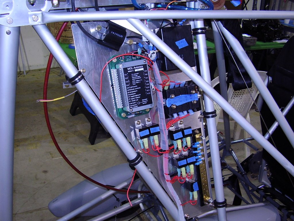
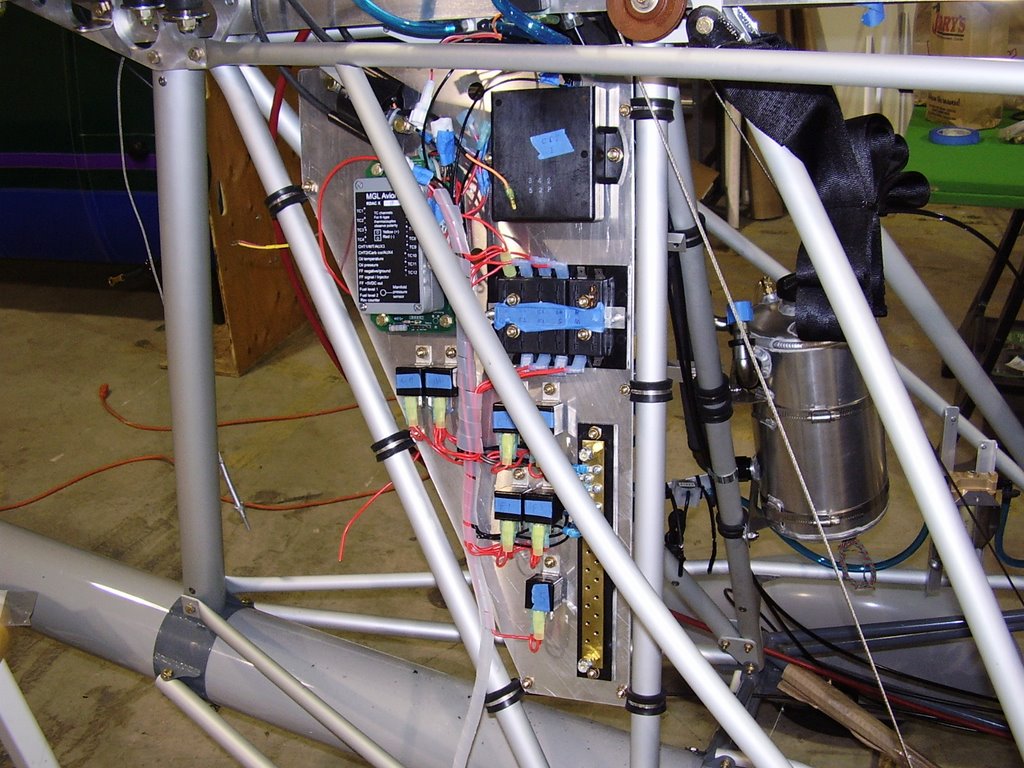
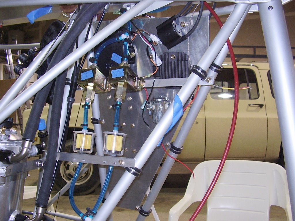
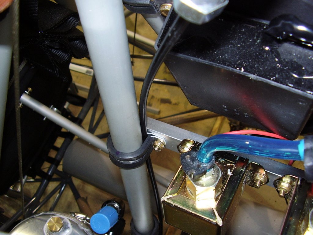
Below are some pictures of the high current wiring I implemented today. I started off with some 6 AWG wire and some copper lugs. I measured and cut the wires to length. I then soldered the copper lugs onto the wires. This was pretty easy after I got the hang of it and let the soldering iron heat up completely. I then cleaned the solder flux off and put some heat-shrink tubing over the connections.

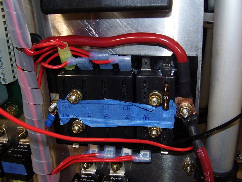
Unfortunately, I used too much solder on one of the wires. The solder wicked up into the wire and prevented it from bending where I needed it to. Luckily this was on the short wire between the fuse panel and the starter. I replaced the wire and reused the copper lugs.


Friday, May 12, 2006

Electrical Panel - 5 hours (253 Total)

Today I replaced my cardboard mockup of an electrical panel with a sheet metal version. I was able to find some 1/16" scrap aluminum sheetmetal at the local metal recycling yard for $4. It cost me $10 to have two cuts made to it!

After removing the existing panel, I transferred the dimension for the holes over to the new panel making some slight alterations. For the items that have multiple bolts holding them in place, I drilled the holes a little larger to allow for slop in my measurements.

After cleaning up the sharp edges, I moved the electrical items over. I was able to move the majority of the items (fuse block, RDAC, Relays, and ground bar) over in one piece without having to remove all of the wiring. This saved a lot of time and hassle.


Thursday, May 11, 2006

Choke Lever - 2 hours (248 Total)

Below are some pictures of my mounted choke lever. I bought the choke lever that Hpower sells for the HKS engine but the lever it comes with does not fully actuate the chokes. I was also having trouble finding a location to mount the supplied lever due to the cable being too short (I even bought Hpower's long choke cable assembly).

I ended up hacking off the supplied lever and replacing it with a lever from a bicycle store. This lever is friction based and mounted nicely to my flap lever. I considered mounting the choke lever to one of the supports under the seat but the lever's built in mounting hardware did not allow it to be rotated and would only easily fit a 1" diameter tube. I needed to use a wire stop at the lever since I do not have a cable of the exact length. I could have one made now that I know what the length is. Hmmmm... That would clean up the wire end that is protruding from the lever and remove the need for the wire stop.

Placement of the choke lever was tight due to interference with the throttle level and the arm-rest. I made sure the choke cable would not interfere with the motion of the flap lever. The third picture shows the lever fully actuated with full flaps.


Fuel Filters - 1 hour (246 Total)

Below are some pictures of the fuel lines that route to the two fuel filters. During the installation of the lines I tried removing the lines above the filters which were installed a few weeks ago. I was unable to remove the lines, all though I didn't try too hard.

I may consider changing the layout of the fuel filters to allow quick release joints above and below the filters. This will allow the filters to be replaced easily but will require a set of quick release connecters to become disposable.


Fuel Flow Sensor - 1 hour (245 Total)

Below are some pictures of my mounted Fuel Flow Sensor. I mounted the sensor with two zip ties to the oil tank support bracket. This isn't very elegant but sensor does not need much support.

I'm not too happy with the fuel line routing. I have a slight angle to the Fuel Flow Sensor as the instructions say to but I do not know if it will be enough. The angle allows air bubbles to escape the sensor. I am afraid that the planes attitude during flight will negate the angle in of my sensor.

I also don't like how the fuel line is rubbing on the oil tank bracket. I placed a piece of fuel line over the sharp edge of the oil tank bracket but I am still not happy with it.


Gascolator - 2 hours (244 Total)

Below are some pictures of my mounted gascolator.

I have only riveted the tops of the angle aluminum that holds the gascolator to the fuselage. I will rivet the bottoms of the angle aluminum after I have installed the sheetmetal skin. The aluminum tube is not secured to the frame so it can shift up and down. I assume this is done to allow alignment with the sheetmetal skin.

I placed a piece of adhesive foam rubber inside the gascolator bracket to keep the gascolator can from rattling against the bracket.


Fuel Tank Selector - 2 hours (242 Total)

In the pictures below you will see how I mounted my fuel tank selector valve.

I wanted to mount it in a left/right orientation so the selection would intuitively point to the left wing tank or right wing tank. Unfortunately, I could not find a location that would allow this so I settled for the up/down orientation. I assume I will have to label to selector anyway to conform to the Sport Pilot regulations.

I have connected the outgoing fuel line which goes to the gascolator. I have not decided how I intend to route the fuel lines from the tank to the selector valve. If I intend to detach the wings, I should consider some type of connector that would allow me to disconnect the fuel lines as they run from the wings into the fuselage. Having the fuel lines run directly from the wings to the selector valve would be the easiest in the short term but would make removing the wings would be a painful process.


Sunday, May 07, 2006

BRS and Seatbelts - 2 hours (240 Total)

Today I mounted the BRS activation handle and right seatbelt.

The BRS activation handle is mounted to the same bracket that the right side seatbelt mounts to.

I connected the activation cable to the rocket so it is now live! I replaced the safety pin with a 3/16 bolt so I didn't have to worry about the safety pin and warning label being inadvertently removed.

I used locktite on the two bolts that hold the rocket mount, on the threaded cable connection to the rocket, and the clasp that holds the rocket bridal to the parachute.


Saturday, May 06, 2006

Battery - 2 hours (238 Total)

Today I placed the battery and BRS rocket.

When installing the hardware for the BRS parachute, I spaced the hardware so the battery would fit between the aluminum angles.

Since the battery is resting on two bolts which hold the aluminum angle in place, I put thick pieces of foam rubber under the battery. This should keep the bolt heads from damaging the batter due to vibration.

I also used some excess aluminum angle to protect the top of the battery from the pipe clamp I used to hold it into place.

The pictures don't show it, but the pipe clamp is also holding onto one of the steel frame members for extra support.


Friday, April 21, 2006

Throttle Cable - 1 hour (236 Total)

Today I finished routing my Throttle Cable.


I used two wire stops with a small gap between them. I will verify the gap during pre-flight inspections to insure the main stop has not slipped. I used locktite on the threads.


I rotated the bolt that hols the friction block. It appears that the bolt will be easier to tighten in this configuration (nut facing inside).


Since I only had one throttle cable to route to the throttle lever, I hastily drilled the screw holes and cable exit hole in the red cable housing gripper without measuring. Of course the cable exit hole didn't line up with the pre-drilled hole in the lever. I ended up trimming the red cable housing gripper to allow the holes to line up.


I place the throttle cable inside of the cable bracket that is holding the fuel pump rail. This holes the cable nicely and eliminates the need for a wire tie but I imagine I'll be cursing it when I need to service the cable.


Here you can see a cable holder I bought at the local hardware store. These look a little nicer than wire ties but as Randy would say, "They add weight!" I haven't decided if I'll use them or not.

Thursday, April 20, 2006

Engine Plumbing - 10 hour (235 Total)

Over the course of several days I routed a majority of the engine plumbing. This was a tedious process of positioning and re-positioning trying to get everything to fit well together. The work consisted of routing some oil lines, fuel lines, fuel pressure sensor, fuel distribution box, and throttle cables.

The pictures below do a better job of describing the routing.


Low Temp Oil Return Line.


Oil source line (from tank to engine) on left


Oil lines and tank


Fuel Lines from Pumps to Distribution Box


Fuel lines between pumps and filters


Fuel Pressure Sensor


Fuel Pressure Sensor


Fuel Distribution Box.


Fuel Distribution Box and Throttle cables.