Sunday, July 23, 2006

Instrument Pod - 5 hours (302 Total)

I am now at the point where I can start finishing up my instrument pod. I recently received the handheld radio that I plan to use with my plane. I will mount this with velcro to the right side of the instrument pod.

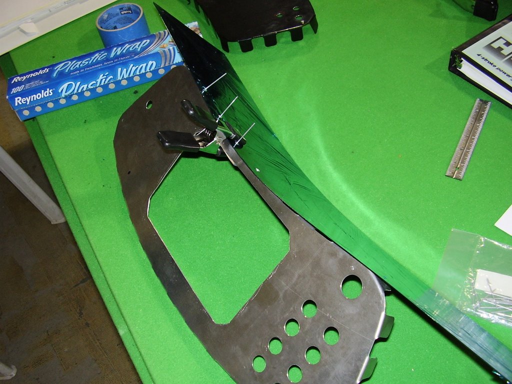
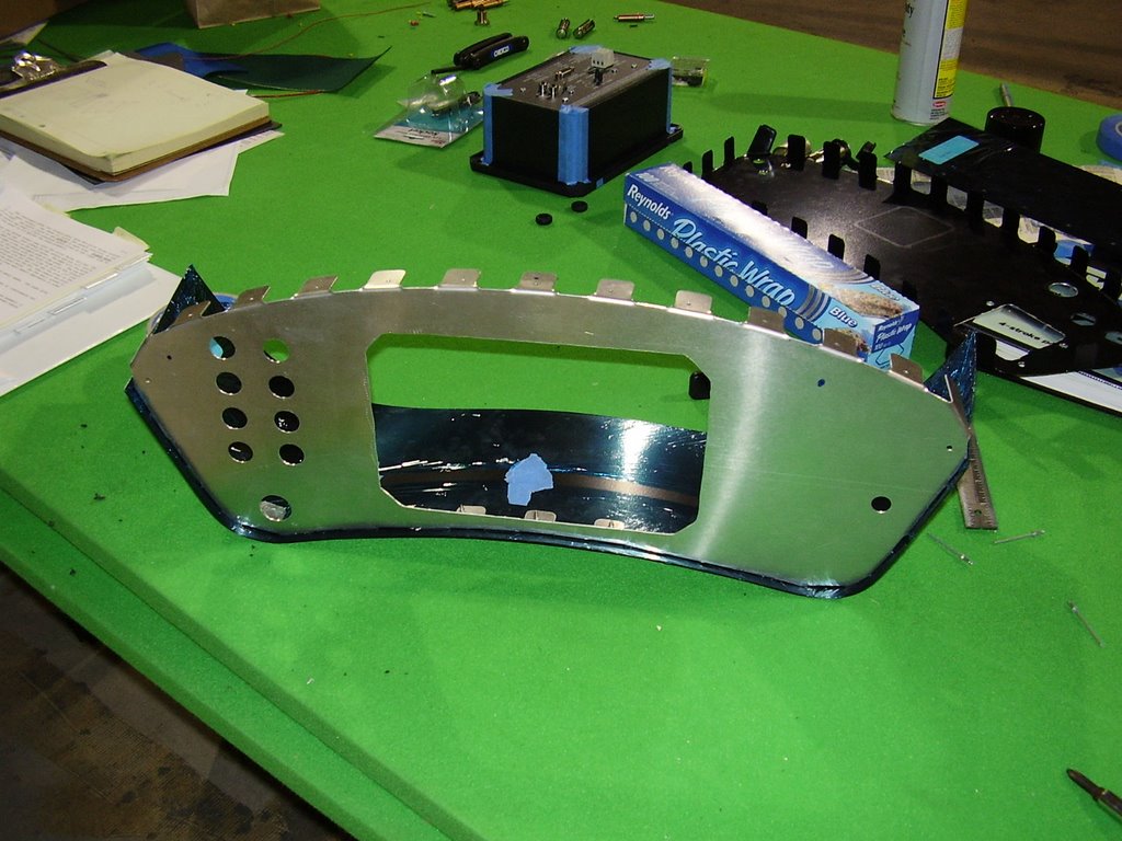
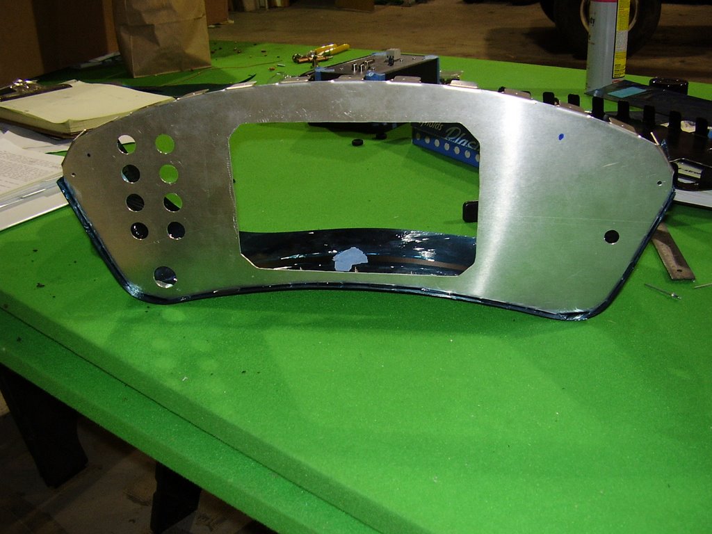
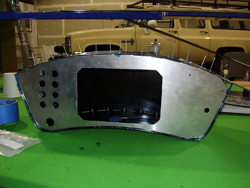
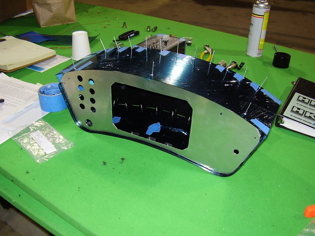
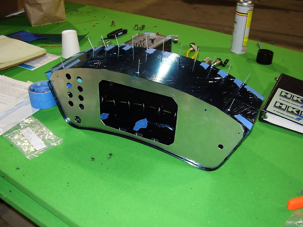
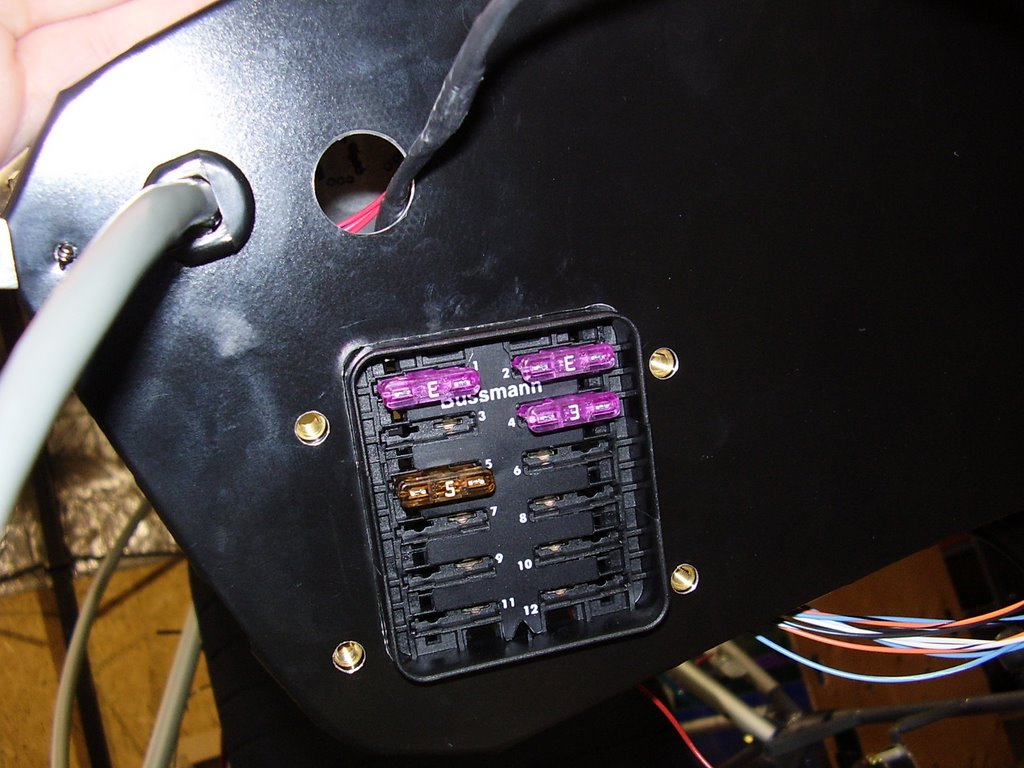
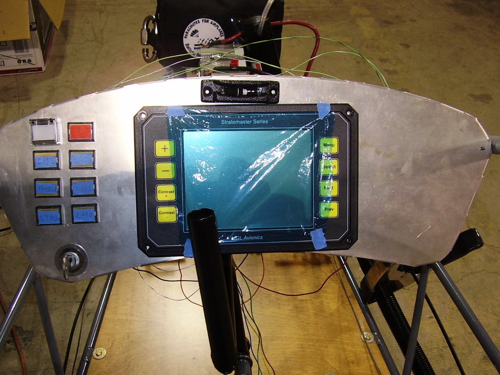
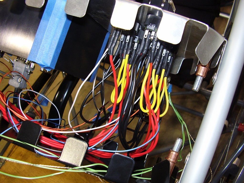
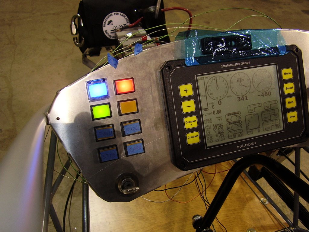
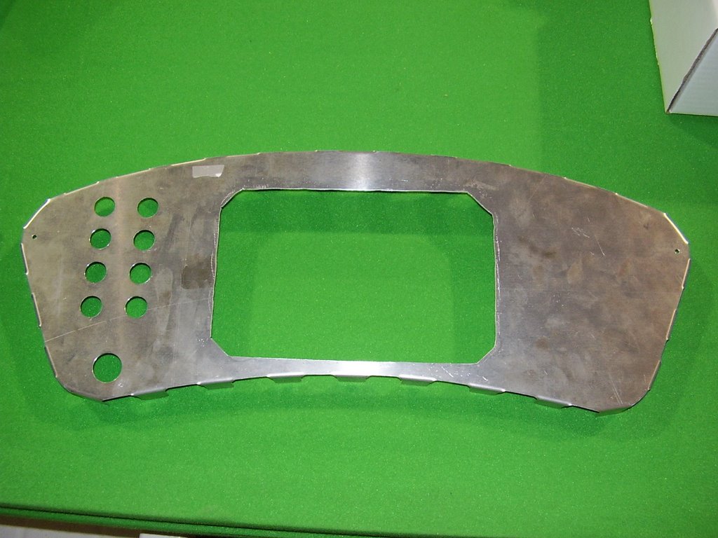
I removed the switches, wiring, and Stratomaster from the instrument panel. I then drilled a hole on the far right of the panel to allow for a power cable for the radio. You can see the hole drilled for this purpose in the picture below.

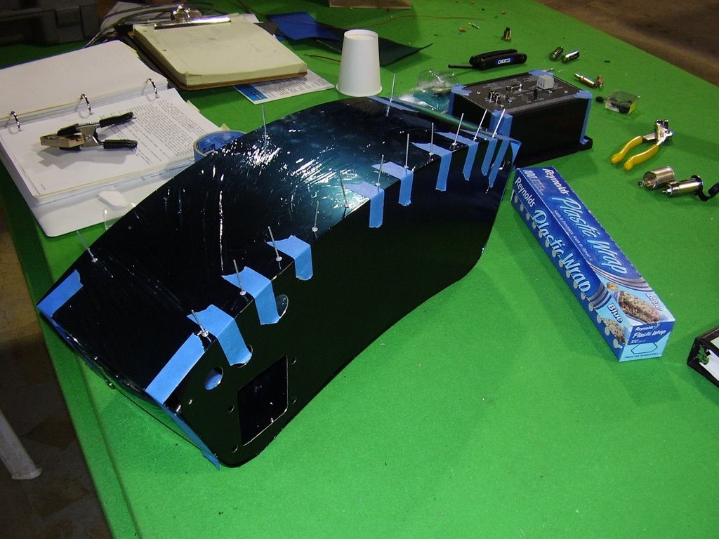
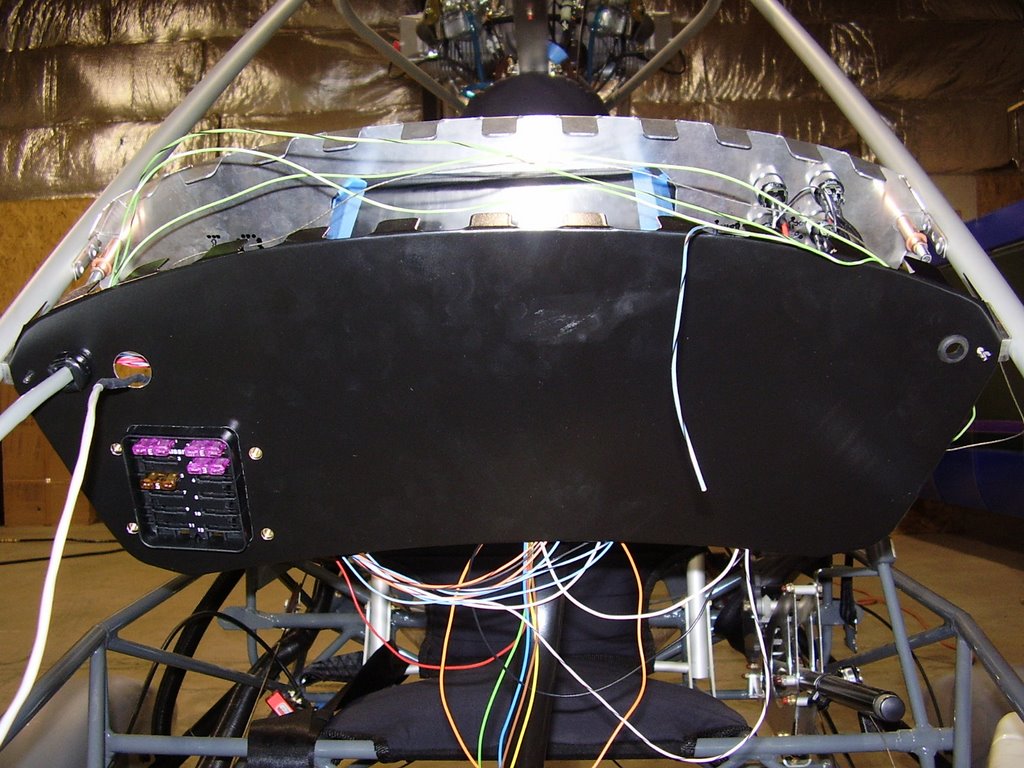
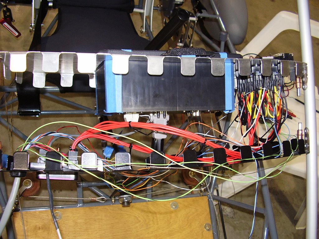
I also drilled a large hole in the backside of the instrument pod for a cigarette lighter and two smaller holes for the headset and speaker jacks. You can see these holes in the last picture.

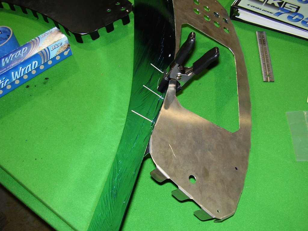
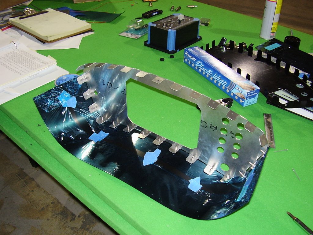
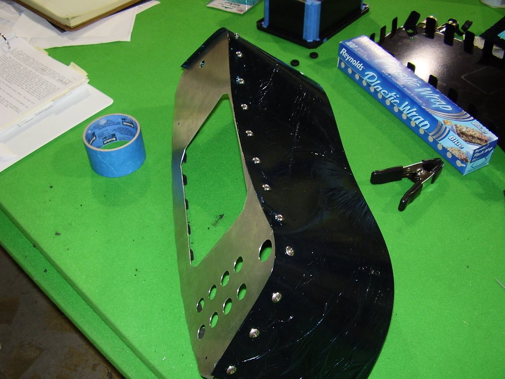
I wrapped the top and bottom panels of the instrument pod in plastic wrap to protect them from being scratched while I assembled the panel. The top and bottom panels were pre-drilled with fastener holes. I needed to transfer these hole to the front and back instrument panels. This was easier than I expected but was still quite tedious.

I started out by riveting the bottom panel to the front instrument panel (panel that faces the pilot) with single rivet in the center. This held the two pieces together securely while I transferred the other holes. Before I started on the holes which are on the curved corners of the panel, I fastened the panel together with the provided sheetmetal screws. This held the panel pieces in place while I bent the bottom panel around the curved corners of the front instrument panel and transferred the remaining holes.

Once I was finished transferring the holes to the front panel, I repeated the process on the back panel. Once that was finished I started the same processes on the top panel. Since the top panel is attached with rivets instead of screws. I was not able to transfer the holes at the very edge of the top panel. I will need to do this when I fasten the top panel in place for good.




Friday, July 21, 2006

Fuel Bracket - 3 hours (297 Total)

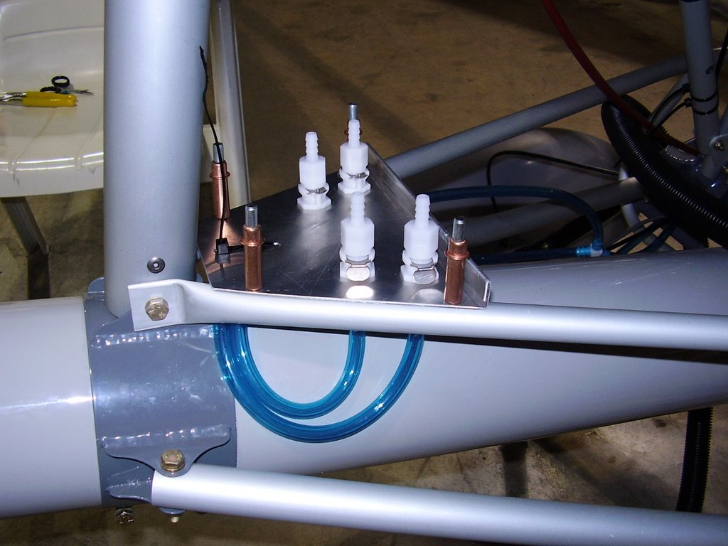
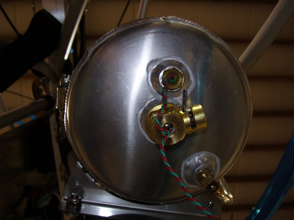
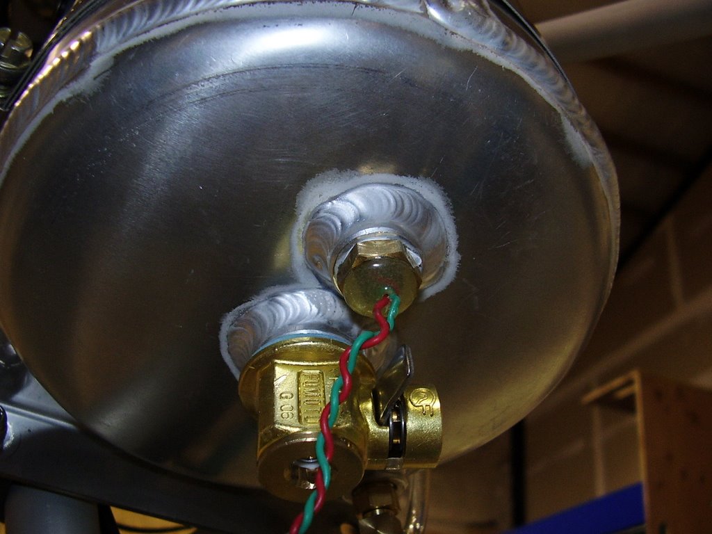
I wanted a way to disconnect my fuel lines to allow easy removal of my wings. To do this I used some quick disconnects with integrated shutoff valves. I selected quick disconnects that mounted into a bulkhead to allow for a solid mounting point.

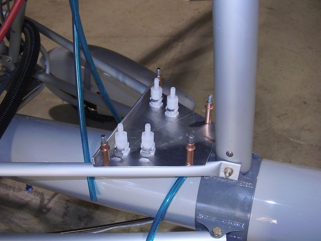
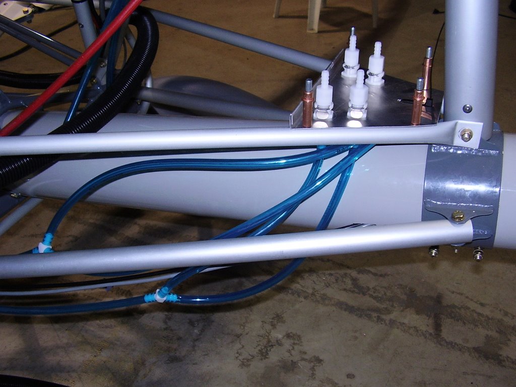
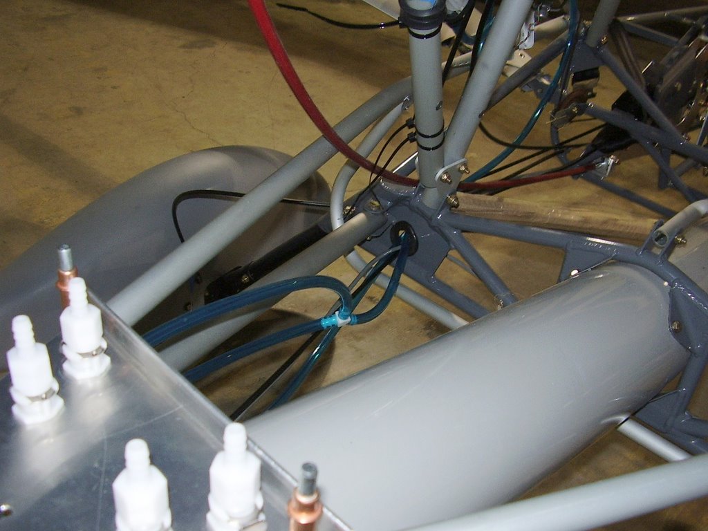
I fabricated a sheetmetal plate or bracket to hold the four quick disconnects. The front of the bracket has a fold to help protect the quick disconnects and keep the bracket rigid.

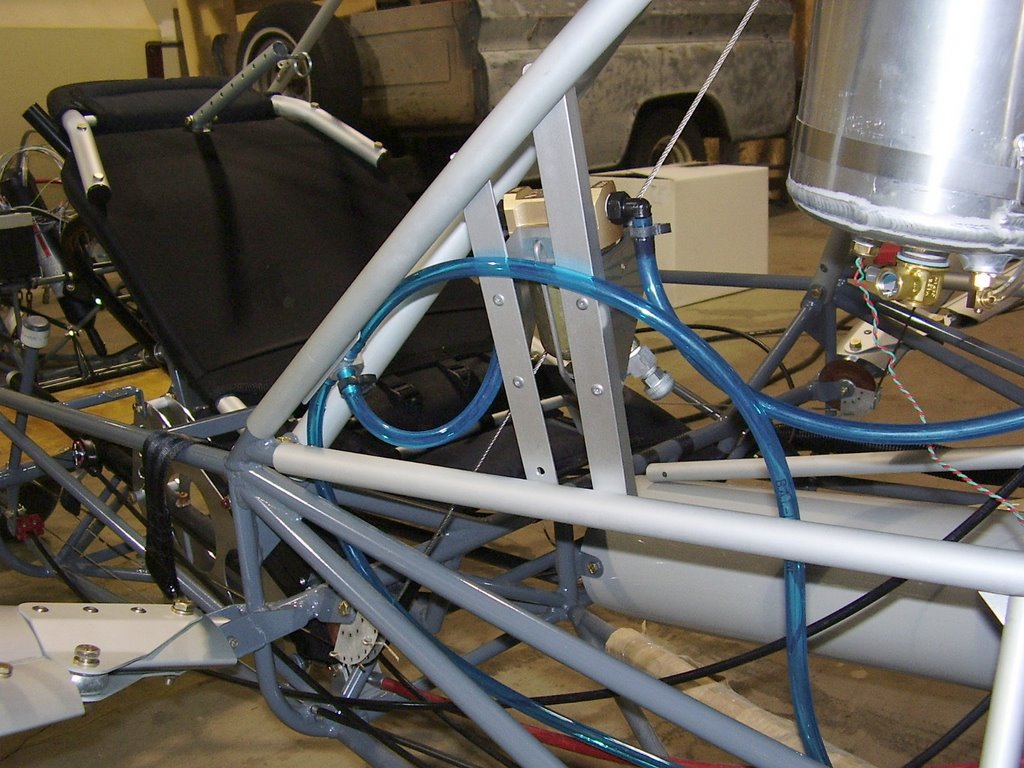
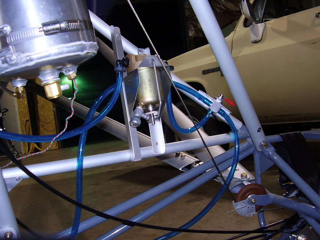
Once this bracket was in place, I was able to complete the fuel line routing from the bracket to the fuel selector valve.


The two wing tanks have forward and rear pickups. The pickups are connected together down-stream from the quick disconnects.


The fuel lines that run from the quick disconnect for the right tank (bottom of above picture) run underneath the bracket and are held in place by a zip tie that is attached to the bracket.


I still need to secure to hoses with hose clamps. I ran out of enough hose clamps to finish the routing.

Wednesday, June 21, 2006

Wing Clearance - 0.5 hours (294 Total)

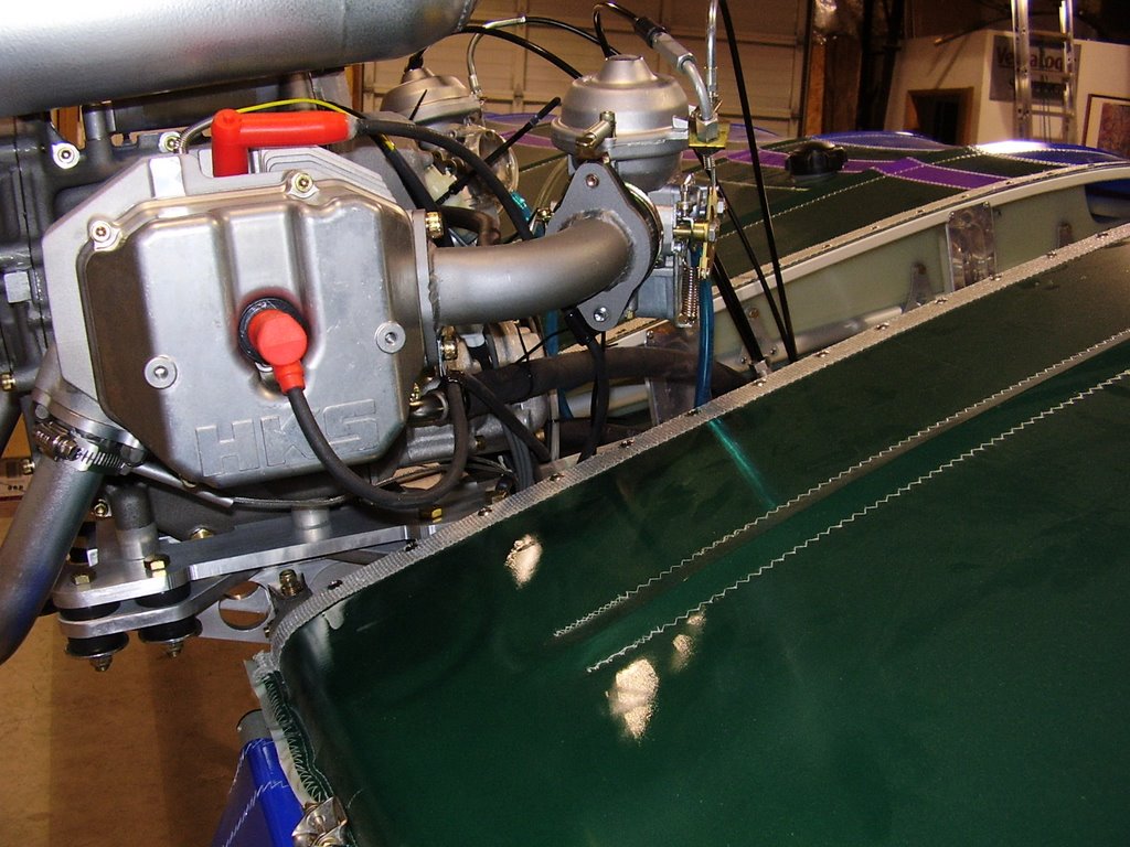
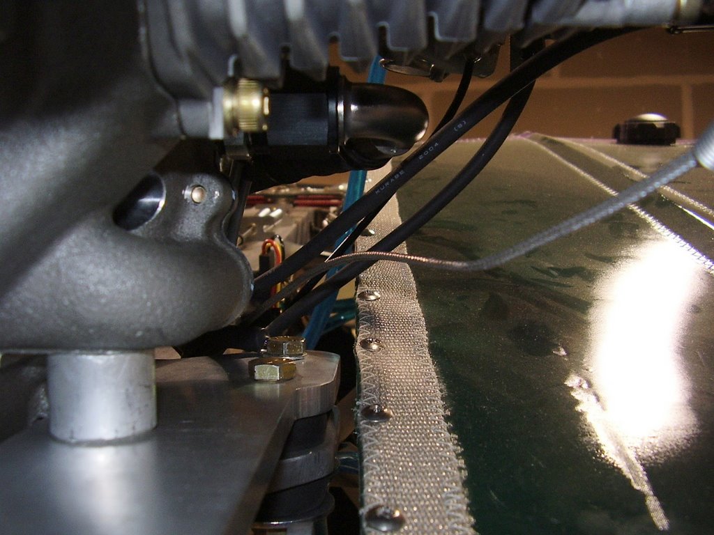
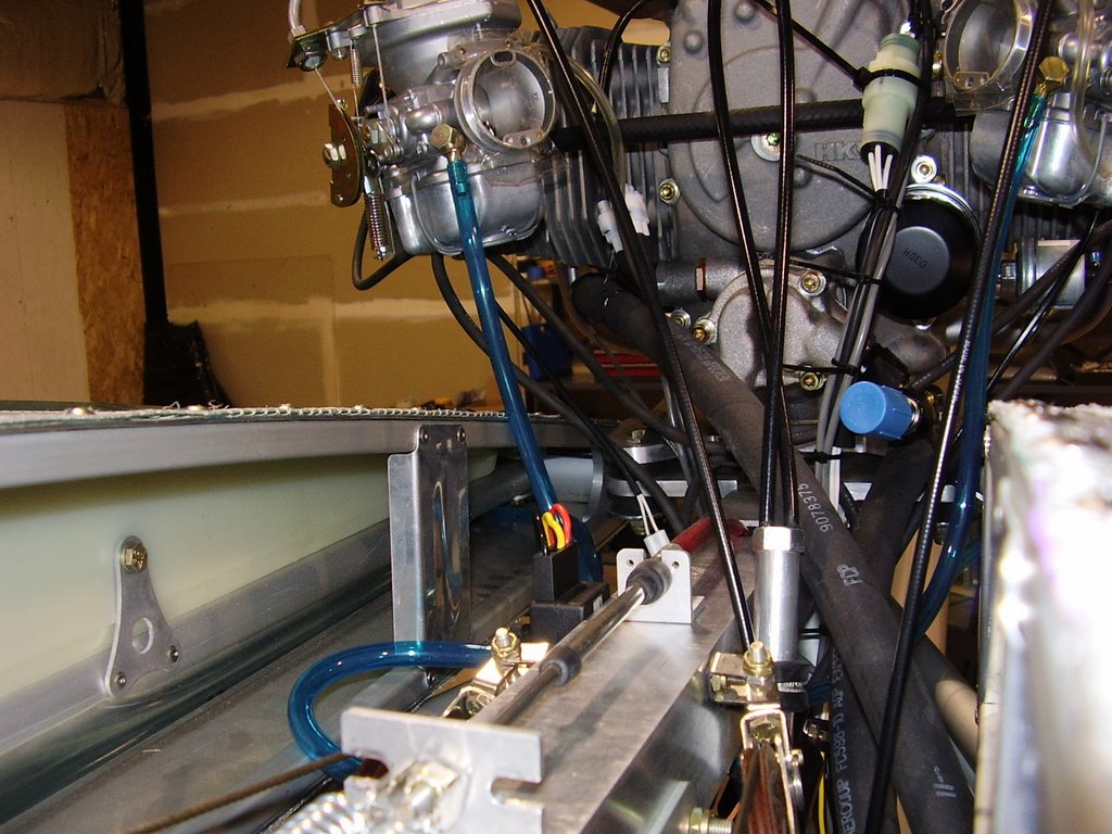
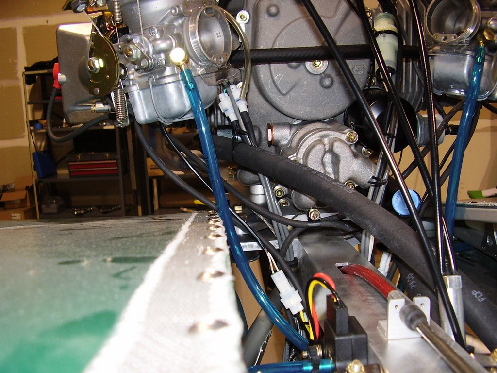
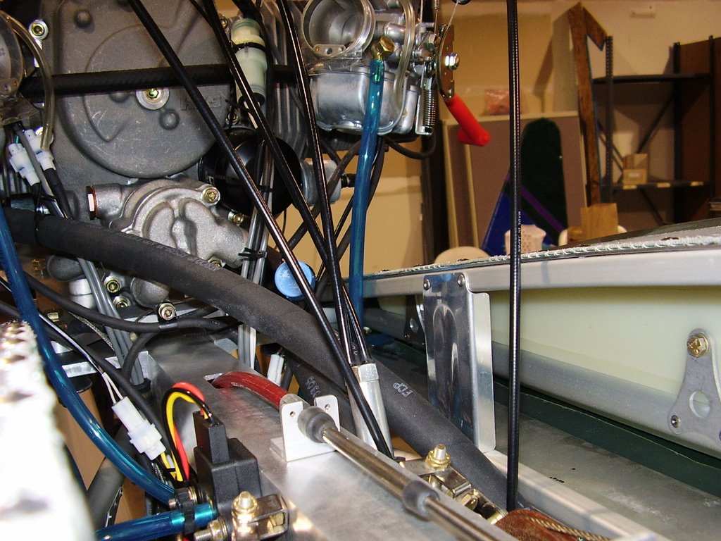
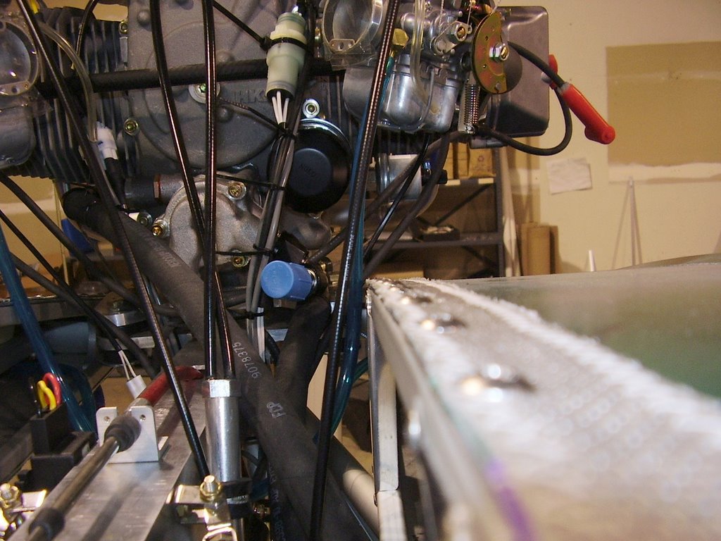
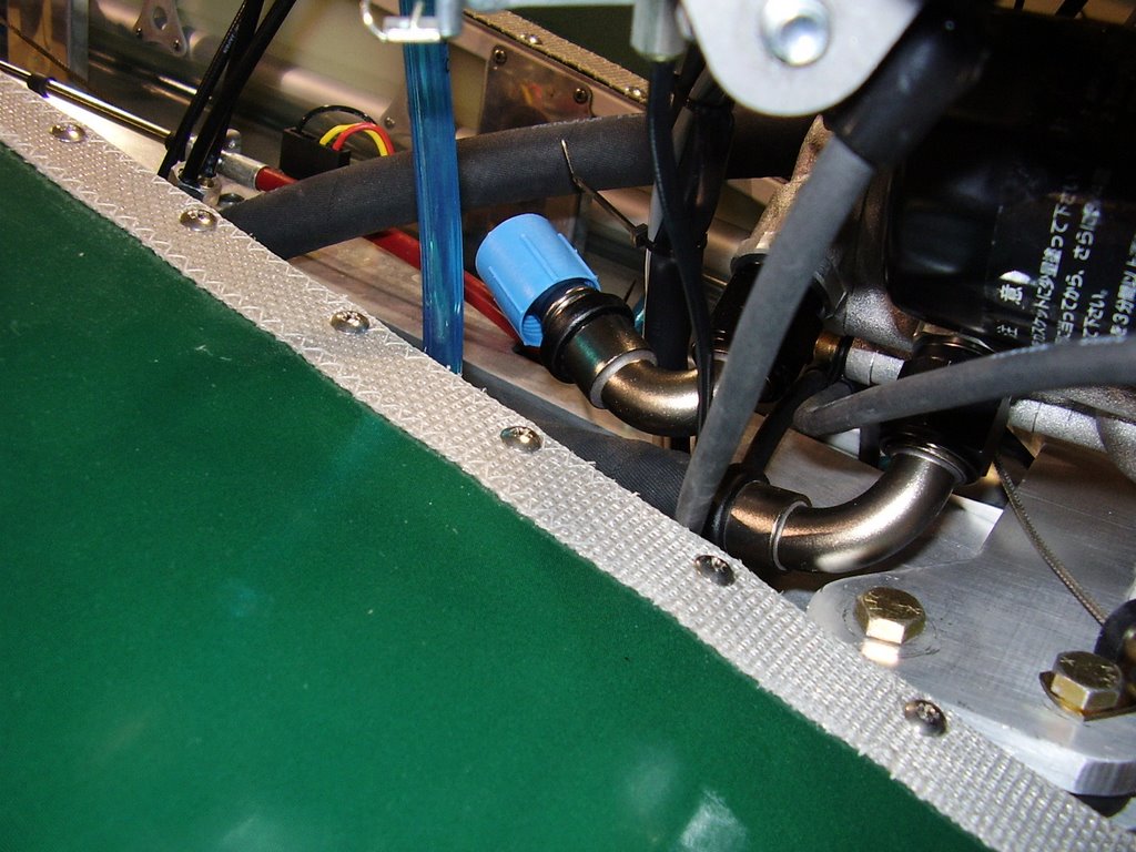
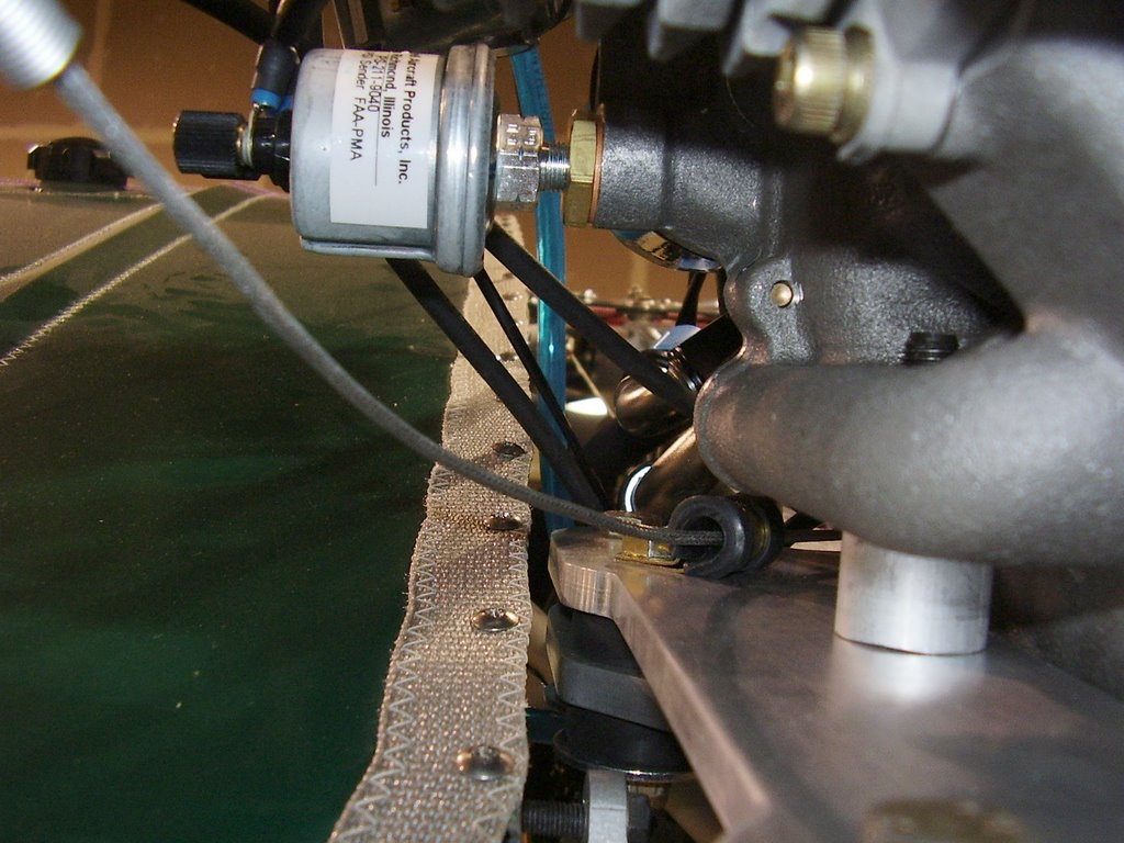
I put the wings back on the plane for the first time since I wired up the engine. There are several wires and hoses that are rubbing the roots of the wings: the fuel lines to the carbs, two of the four spark plug wires, and the fuel line to the pressure sensor.

The carbs have banjo fittings on their fuel inlets. I'll be able to rotate the fittings to increase the clearance on the fuel lines.

The fuel pressure hose will need to be re-routed with a couple of 90 degree fittings.

The sparkplug wires will need to be re-routed. I will remove the clamps that are holding the wires to the intank manifolds and secure the wires to the balance tube with wire ties and standoffs.

Here are some pictures of the items that are rubbing on the wing roots.


Monday, June 19, 2006

Oil Valve - 1 hours (293.5 Total)

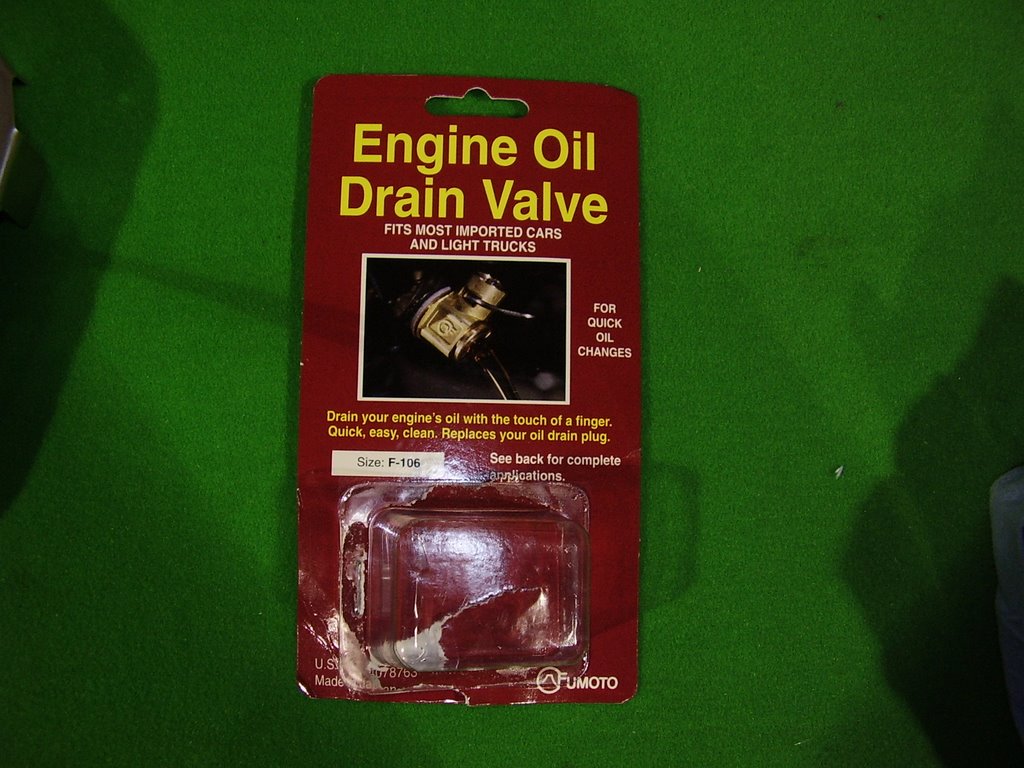
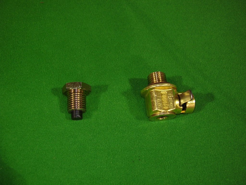
To make changing the engine oil easier. I purchased a Fumoto engine oil drain valve. This valve will allow me to change my oil without the hassle of removing the oil plug. I have heard stories of people dropping the hot oil plug into the funnel they were using to collect the oil. The funnel then overflows and makes a huge mess.


I purchased the F-106 model which fits the 14mm by 1.5mm thread used on the oil tank.


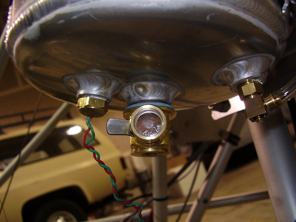
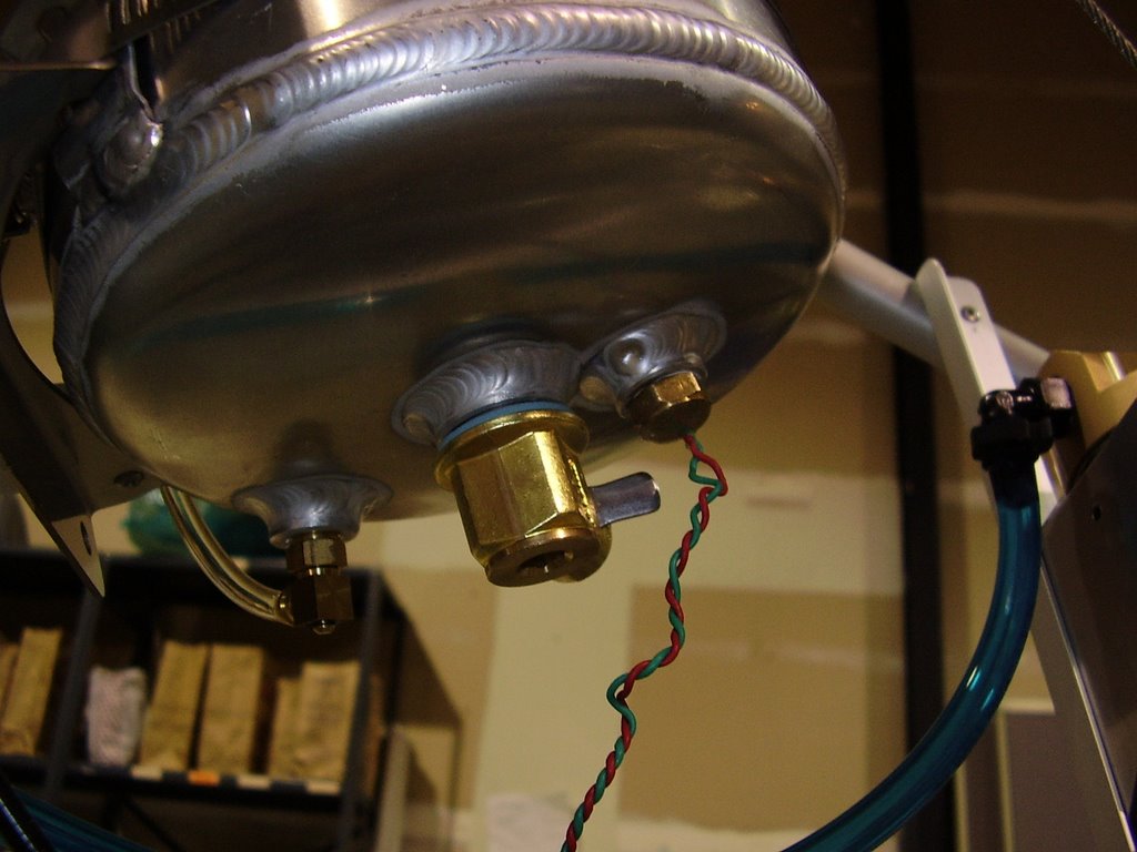
Unfortunately, the valve ran into the oil temp sensor when I tried to install it. I had to remove the temp sensor with the intent of installing it after the valve was fully installed. As luck would have it, the valve seated with its larger end interfering with the temp sensor hole.

To alleviate this, I combined the gasket type washer that came with the valve with the copper washer that was used with the orignal oil plug. This allowed the valve to seat with it's large end pointed in a slightly different direction. I will need to watch the valve for a while to make sure the combination of the washers remain leak proof.


Sunday, June 18, 2006

Instrument Panel - 8 hours (292.5 Total)

Today I started out by cutting out holes in the back side of the instrument panel. In the picture below you can see two holes on the left for the wiring. Below that is a large square hole for the fuse block. On the right side you can see a rubber grommet for pitot tube.


Below you can see the installation of the switches and Stratomaster display. Above the Stratomaster is a coordinated turn indicator. It will be bolted into place when everything is done.


Below are some pictures of the wiring inside the instrument pod.


Below is a picture of the powered on system. You can see that some of the switches are illuminated and the Stratomaster display is turned on.


I tested all of the switches and their functionality except the starter. I don't want to engage the starter until I have the oil system complete.

With the Stratomaster functioning, I tested all of the temperature sensors. I used my hot air gun to verify that I didn't have any of the wiring crossed.

Thursday, June 15, 2006

Instrument Panel - 4 hours (284.5 Total)

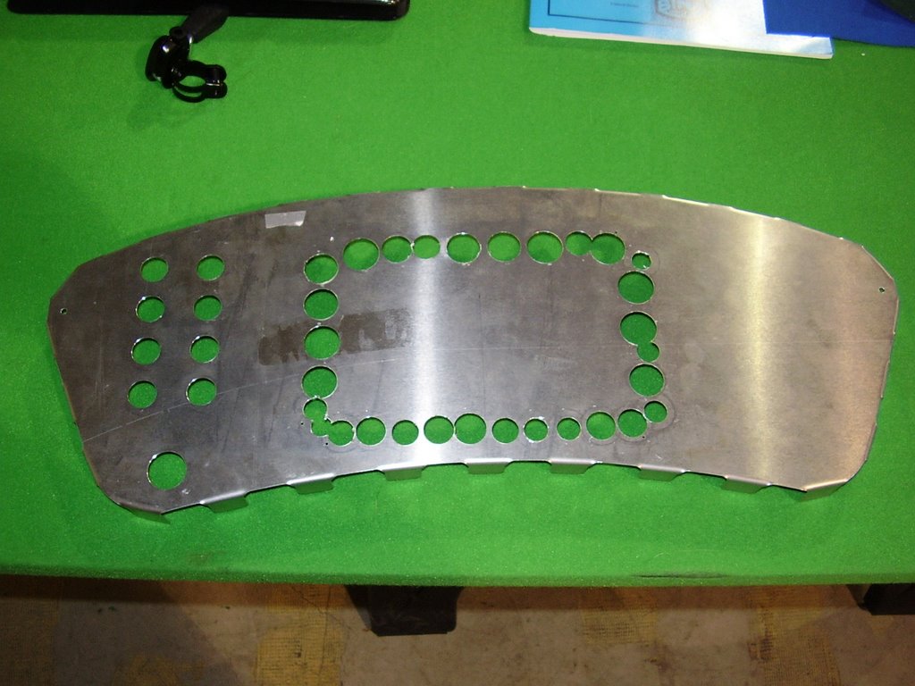
Today I started cutting into my instrument panel. Over the past few months I have been playing with the layout of the panel.

The holes you see on the left will accommodate seven switches, an indicator light, and a key-switch. I drilled these with a drill press and step-bit which I bought specifically for this portion of the project.

The holes in the rectangular pattern were drilled to allow me to use a nibbler tool to cut away a large portion for the Stratomaster instrument display I will place in the dash.


Saturday, June 10, 2006

EGT Sensors - 1 hour (280.5 Total)

Today I attached the EGT sensors to the exhaust.

I had previously located and drilled the 5/16" EGT sensor holes into the exhaust prior to bolting it to the engine. I positioned the sensors' holes so the wiring would point directly towards (at an angle) the egress into the cockpit. I ignored the recommendation to have the holes downwind of the exhaust pipes. A fellow HKS owner has his sensors in the same configuration and doesn't have any problems.

The EGT sensors are almost too long for my exhaust pipes. There is about a millimeter of space between the tip of the sensor and the opposite wall of the exhaust pipe.


Above you can see that I needed a wire clamp to hold the left EGT sensor wire in place.


I made sure that the right cylinder has both EGT1 and CHT1 probes connected to it.

Thursday, June 08, 2006

Exhaust - 4.5 hours (279.5 Total)

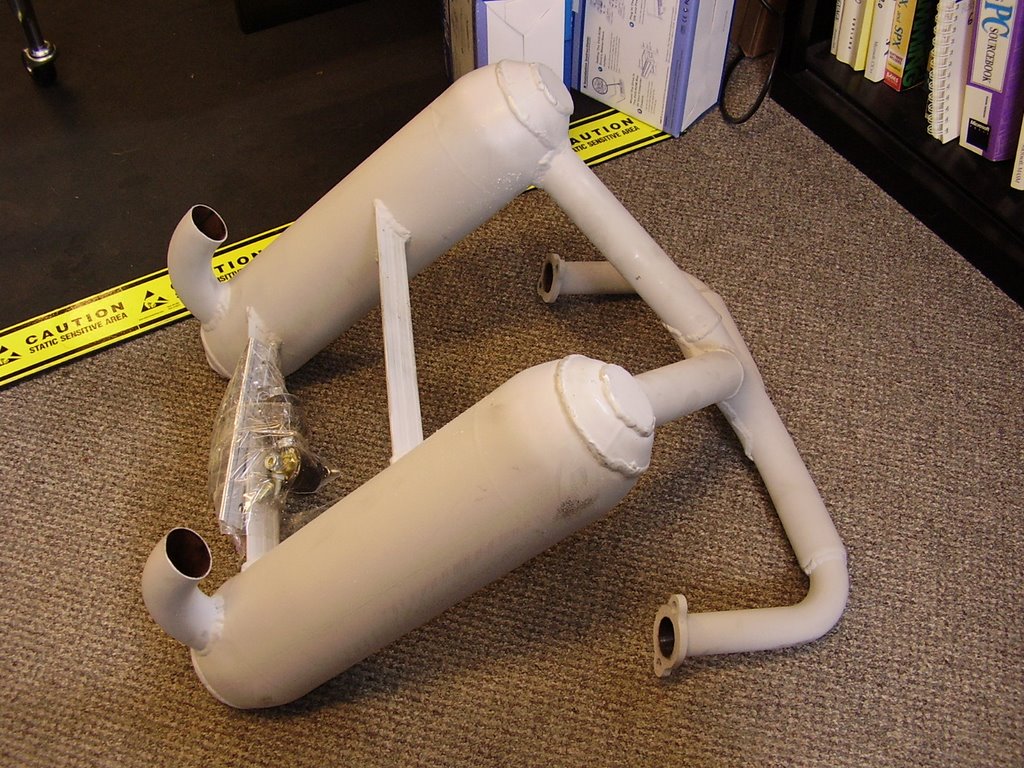
Earlier this week I received my exhaust from Earthstar. Below are some pictures and details of its installation.


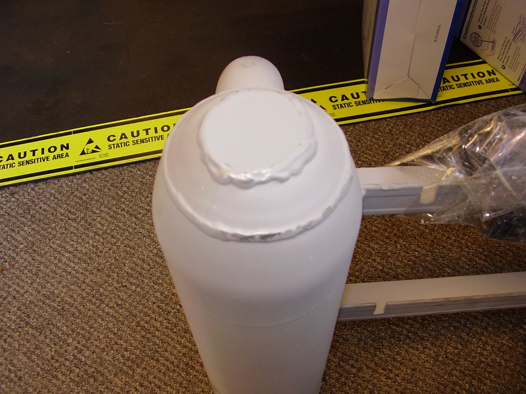
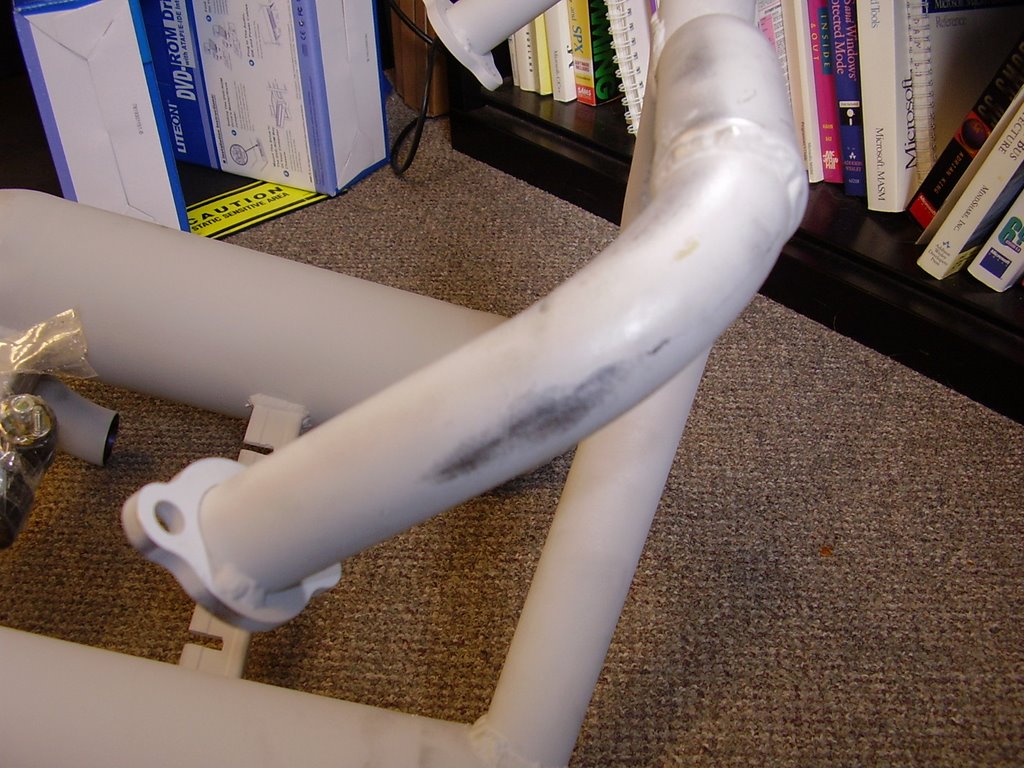
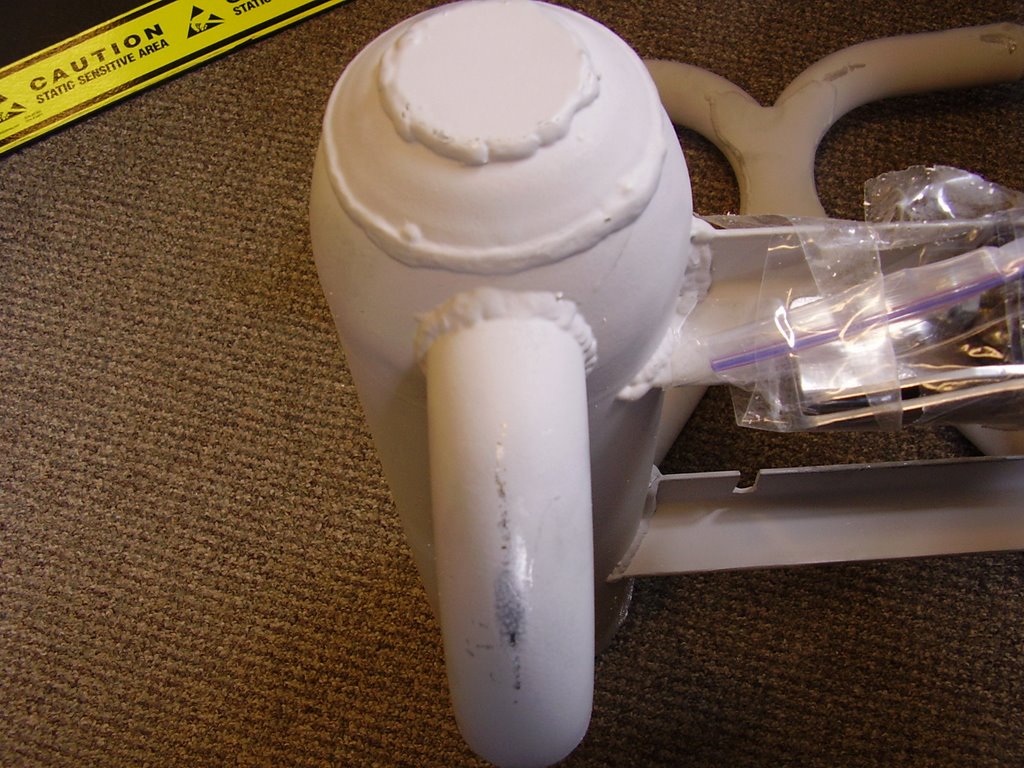
I purchased an exhaust from Earthstar that was already ceramic coated. Unfortunately, no finishing was done after the coating was applied.


I would have been happy with the light gray coloring and powdery texture but the exhaust had several polished spots on it. During shipping, portions of the exhaust that were in contact with the cardboard box or styrofoam polished themselves due to the vibrations.


Another problem with the unpolished ceramic coating is that it picks up dirt very easily. There were hand prints on the exhaust left by the Earthstar people.


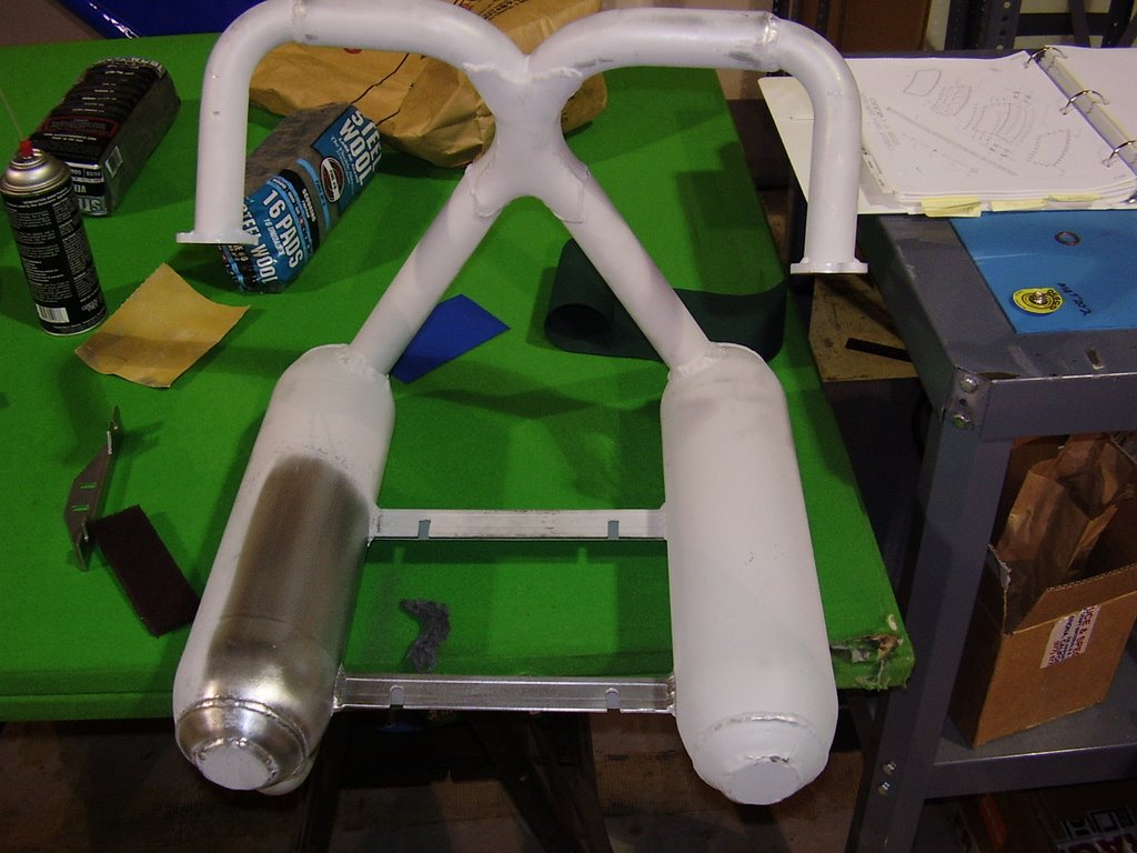
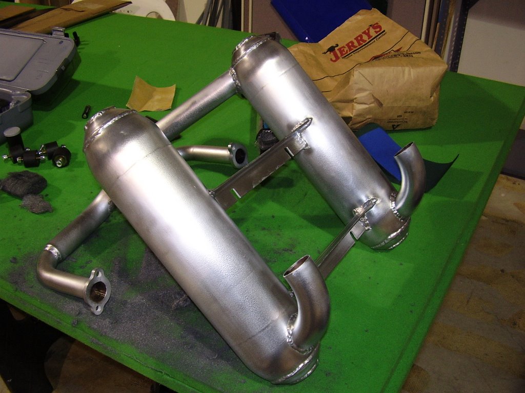
After consulting with Earthstar and Finish Line Coatings, a company in Portland, OR that does ceramic coatings, I started polishing the exhaust with some steel wool. This was surprisingly easy to do.


Here is a picture of the fully polished exhaust. It took me about three and a half hours to polish the entire exhaust.


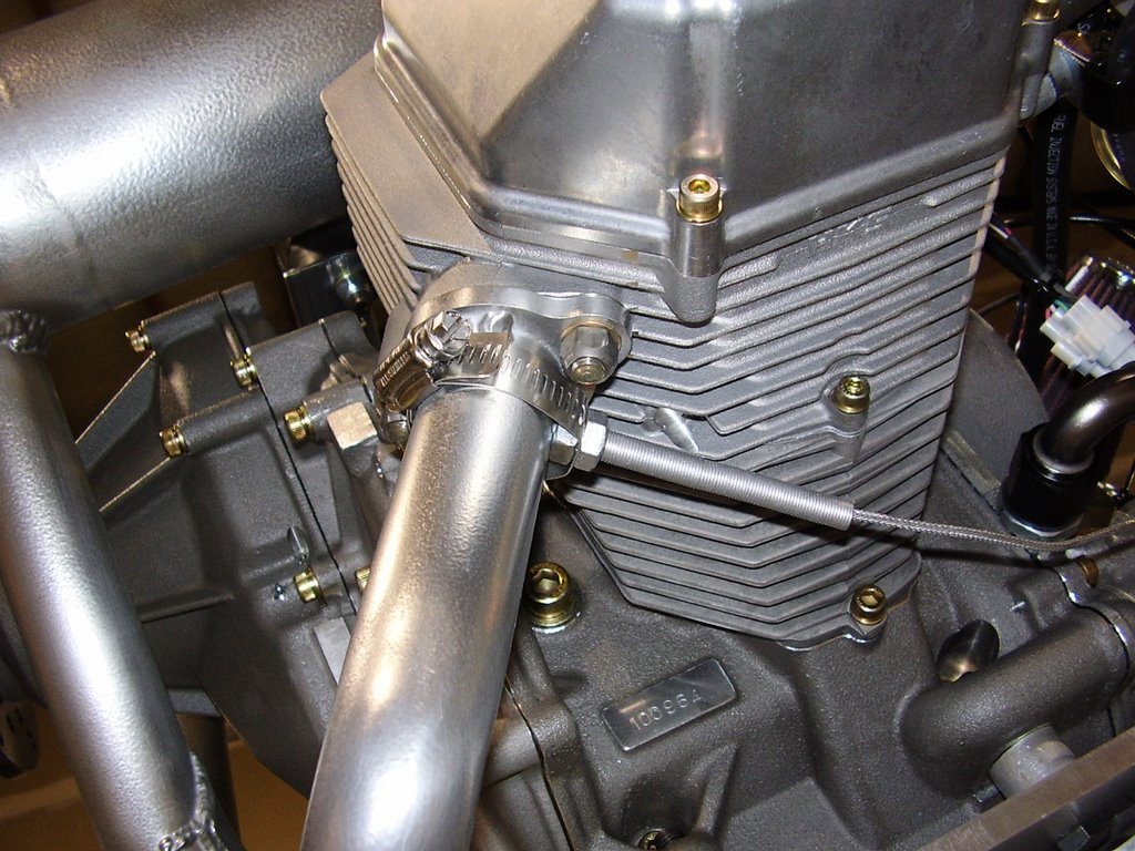
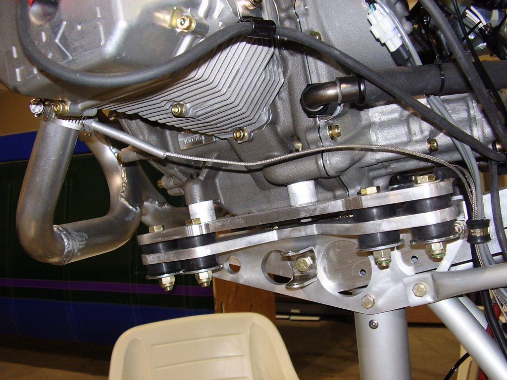
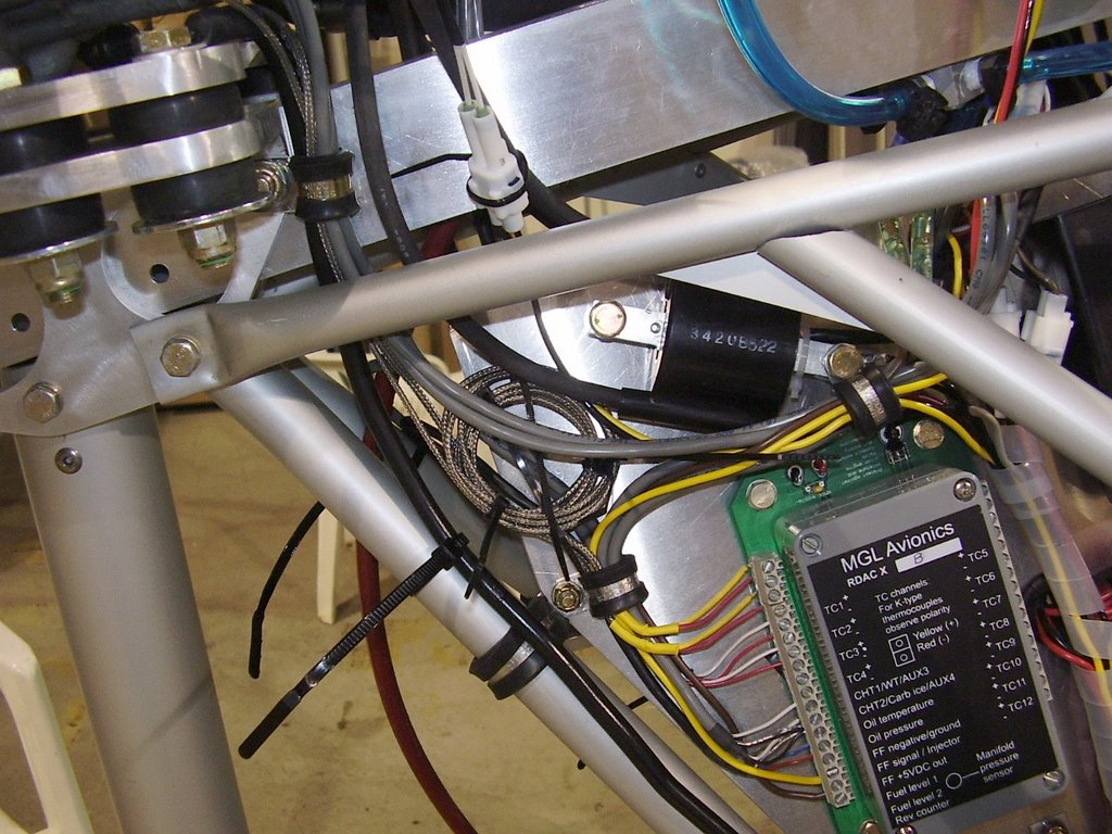
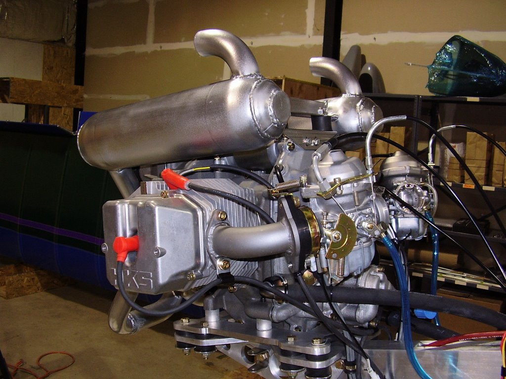
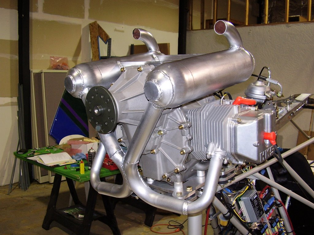
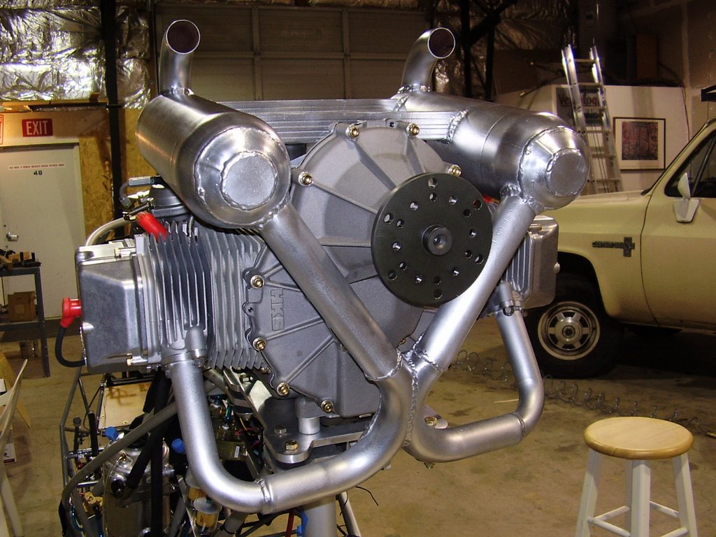
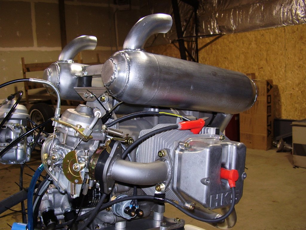
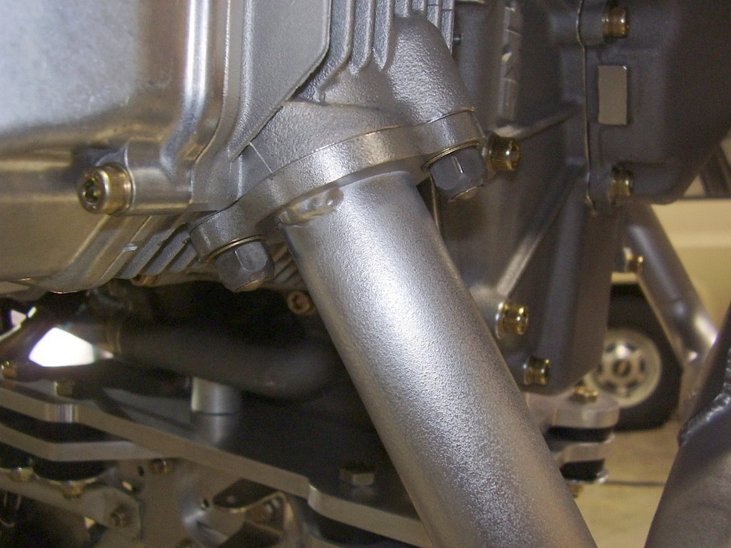
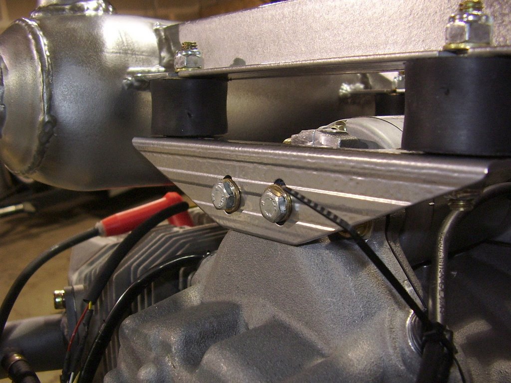
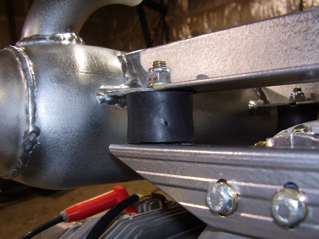
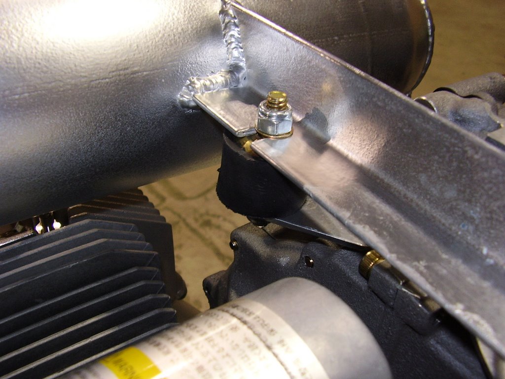
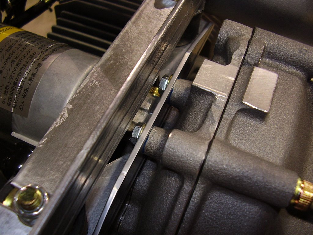
Here are some pictures of the installed exhaust.


To mount the exhaust, I bolted the exhaust to the exhaust ports first. I used some AN washers and supplied gasket. The nuts seem to be self locking (triangular threads) so I didn't use any locktite. Prior to bolting it to the engine, I did drill the holes for the EGT sensors while the exhaust was on the bench.


I then loosely bolted the bracket (pictured above) to the engine.


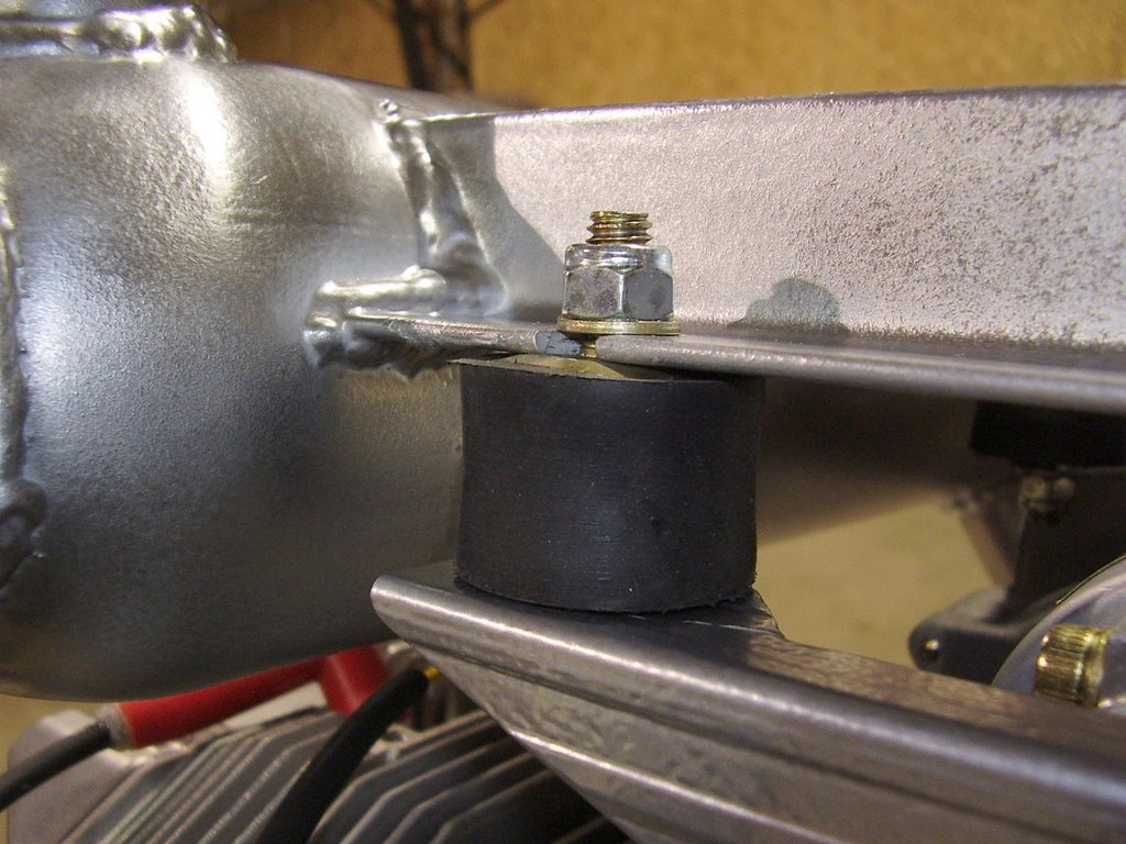
I then bolted the Lord mounts to the exhaust and bracket.


I torqued the nuts on the Lord mounts very tight. You can see the metal plate on the Lord mount popped up and against the bracket. After the Lord mounts were nice and tight, I tightened down the bolts that hold the bracket to the engine using Locktite.


I then repeated the process on the rear bracket.