Saturday, September 02, 2006

Cowling - 3 hours (327.5 Total)

Today I receive my finished cowling and am happy with the results. I was initially disappointed in the looks of the cowl when I had seen the first welded seam. In my last post I discussed several theories on what I thought had occurred since I wasn't there to witness the welding. I was able to watch and help out with the welding of the three other seams. It turns out the problem with the welding was easily resolved by using clamps more often. By clamping the material together an inch to two inches away from the weld, we were able to keep the material from moving or warping. This required a lot of clamp moving but wasn't difficult. My extra set of hands moving the clamp allowed the welder to concentrate on the welding.

Once all four seams of the cowl were welded, we ground off the high points and ran a second and sometimes third bead. This cleaned up the welds nicely.

I still need to secure the oil cooler inside the cowl and cover the large holes on either side.


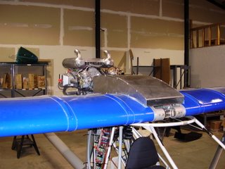
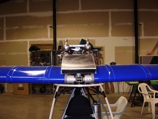
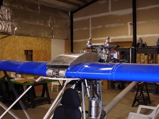
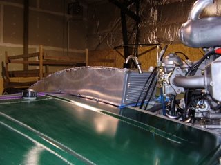
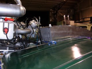
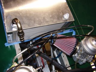
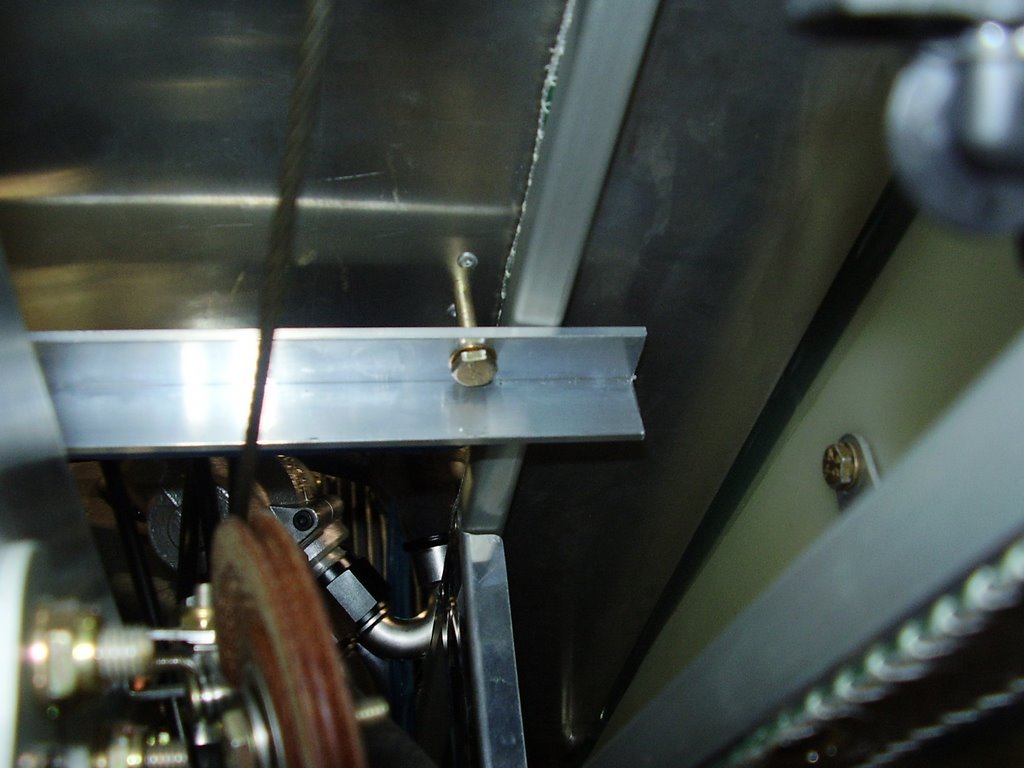
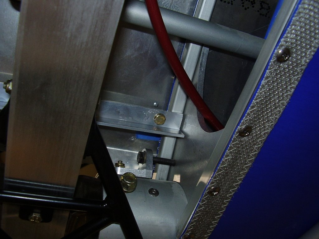
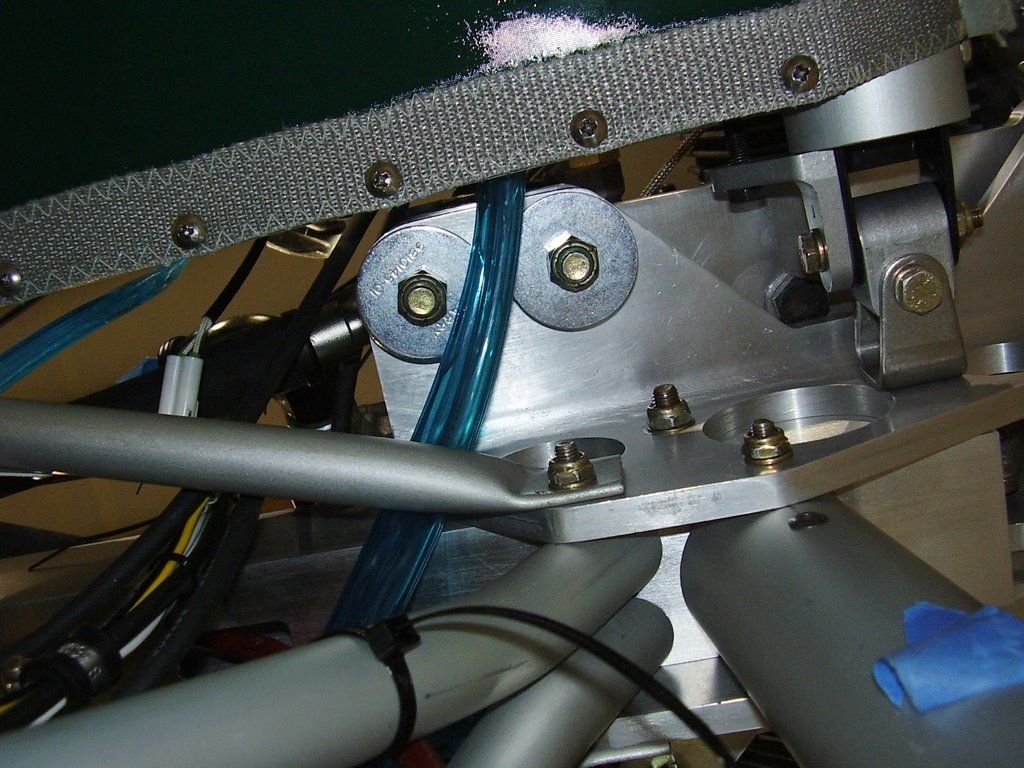
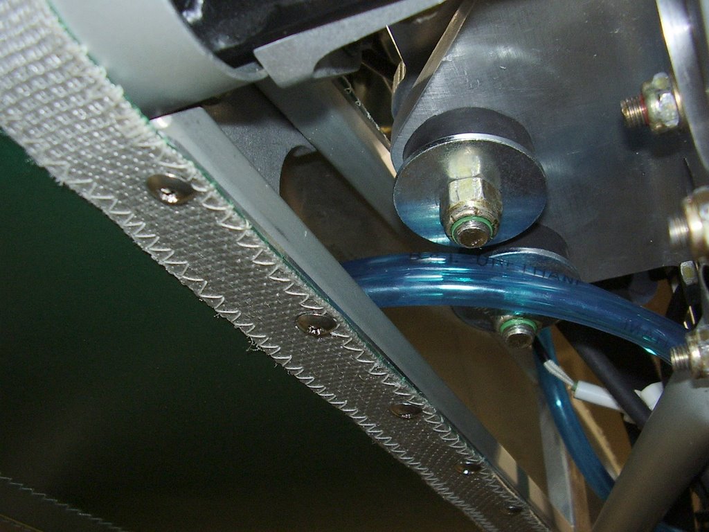
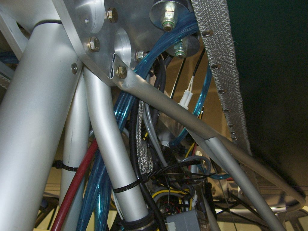
To mount the cowl I installed eight nut plates to the bottom surface of the cowl. I then cut four pieces of angle aluminum. In the pictures below you can see how the four pieces of angle aluminum clamp the cowl to the top edge of the root ribs of the wings. I have a piece of 1/4" dense foam under the cowl to absorb vibration and protect the wing fabric.


The corners of the cowl near the opening are sharp. I will need to round these over to prevent them from coming in contact with the wing fabric and damaging it. I placed blue paper towels under the corners in the mean time. You can also see the nut plate in the picture below.


Wednesday, August 30, 2006

Thermostat - 3 hours (324.5 Total)

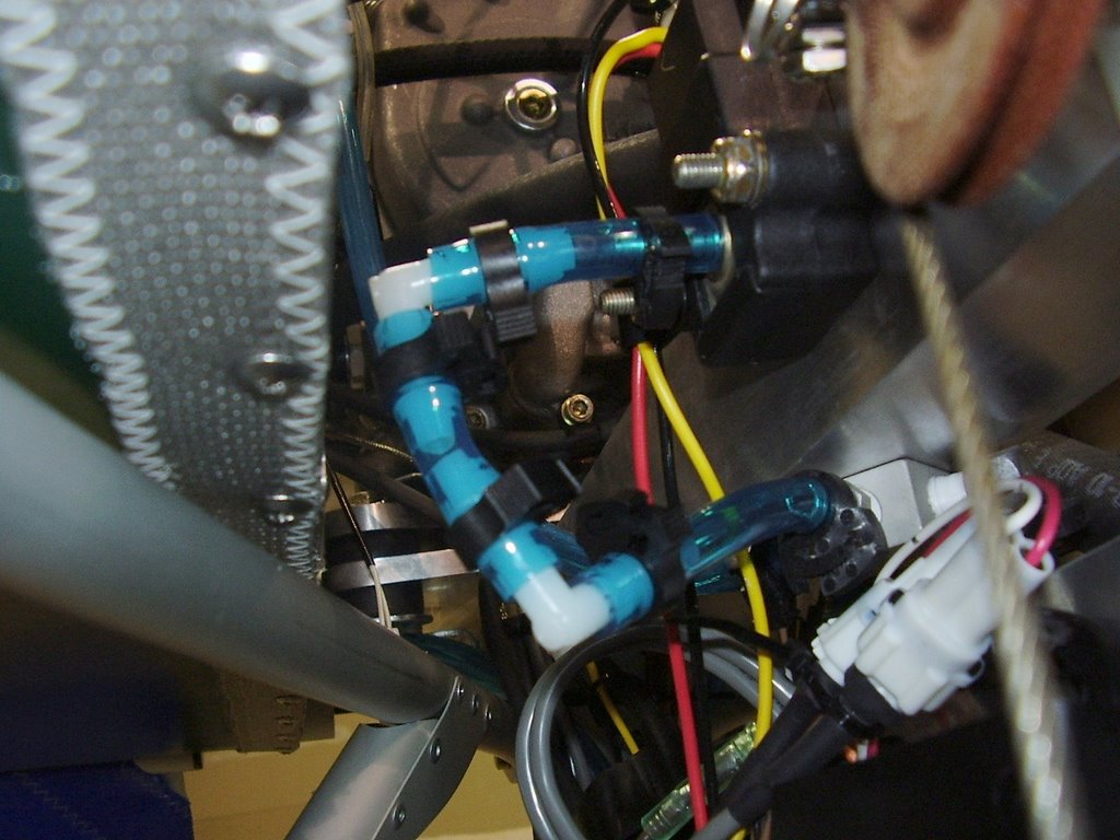
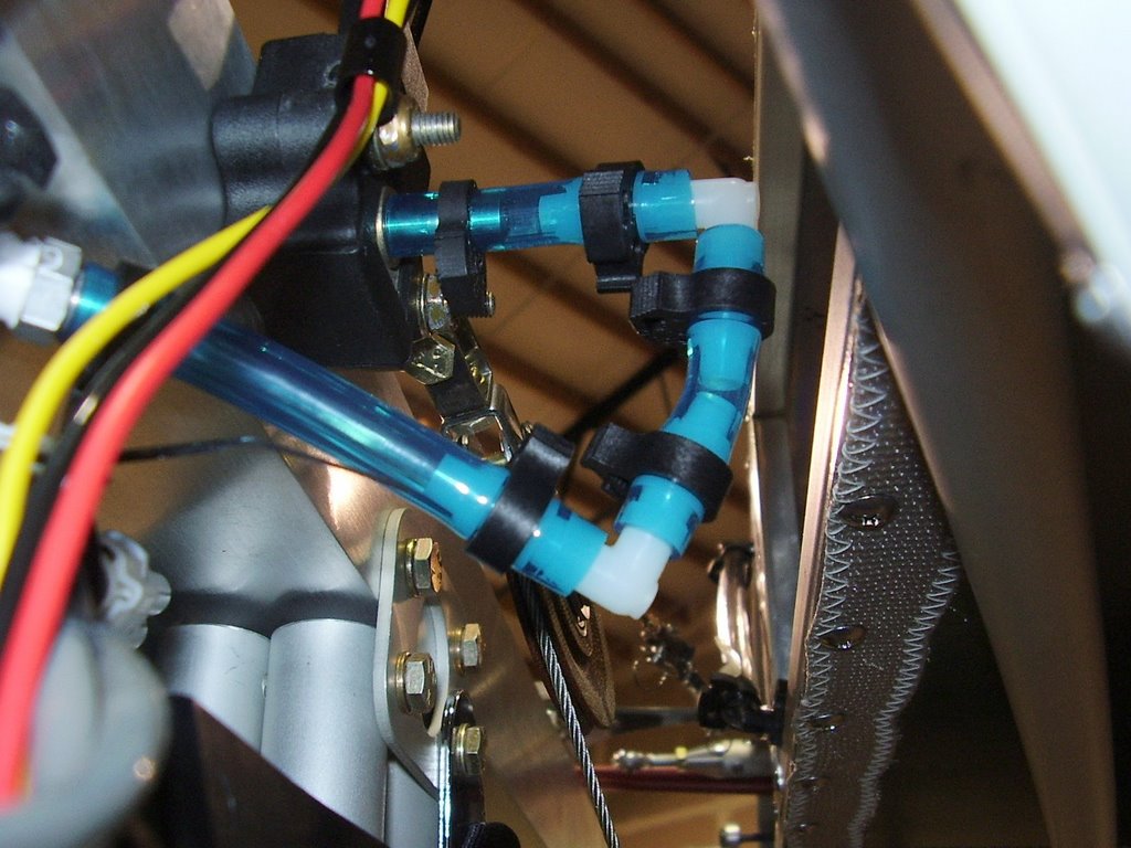
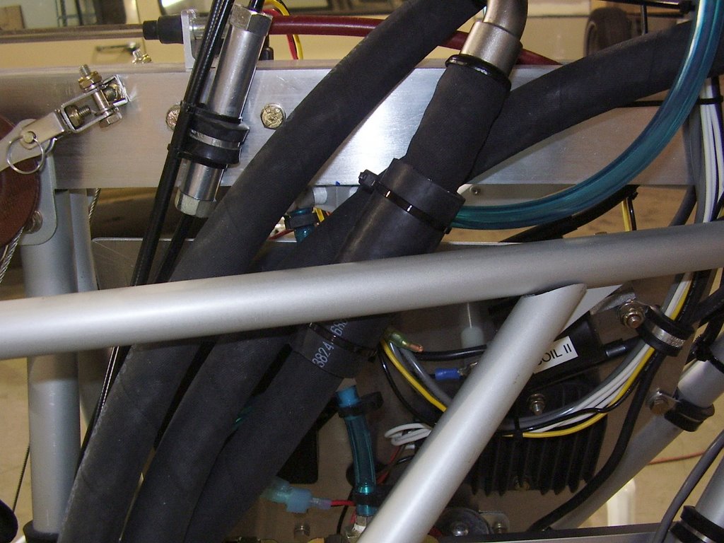
Today I plumbed my oil cooler, thermostat, and oil lines. Unfortunately, I don't have any pictures of the finished setup and at the time of writing this, I have already taking the cowl and wings off the plane. I have a couple of pictures in my September 9th post that show the plumbing with the cowl and wings removed.

I did not have a lot of room to place the oil thermostat between the cooler and the engine. I needed to orientate the thermostat at an odd angle to allow the oil fittings to clear all of the engine components. For the hose that connects the thermostat to the engine, I needed to use two 180 degree fittings.

The tight space required the use of short hoses which actually helped in mounting the thermostat. These short hoses give enough structure to the thermostat that it doesn't need to be physically mounted.

Before cutting my expensive oil lines to length, I used a cheap hose to mock up the plumbing. This worked great but I ran into one issue when I started replacing the cheap hose with the Aeroquip hose. When the Aeroquip hose is pushed onto the fittings, the hose looses 1/2" of length. This usually isn't an issue with a longer hose but caused me some problems on my 6" hose. Luckily, I was able to use that hose in a different location since I didn't have any to spare. I had only ordered 8' of the hose and ended up using all but two inches of it!

I was forced to route one of the oil lines in a way that could cause it to chafe against the structure. I ended up placing a rubber hose around the oil line to protect it. This isn't the most elegant fix but it is a common way of dealing with these issues. You can see a picture of this in my September 9th post.

Sunday, August 20, 2006

Cowling - 0 hours (321.5 Total)

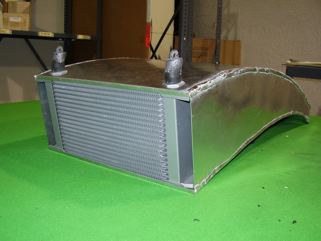
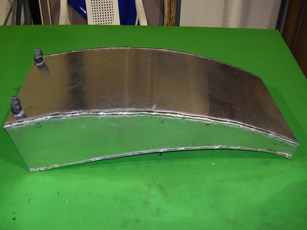
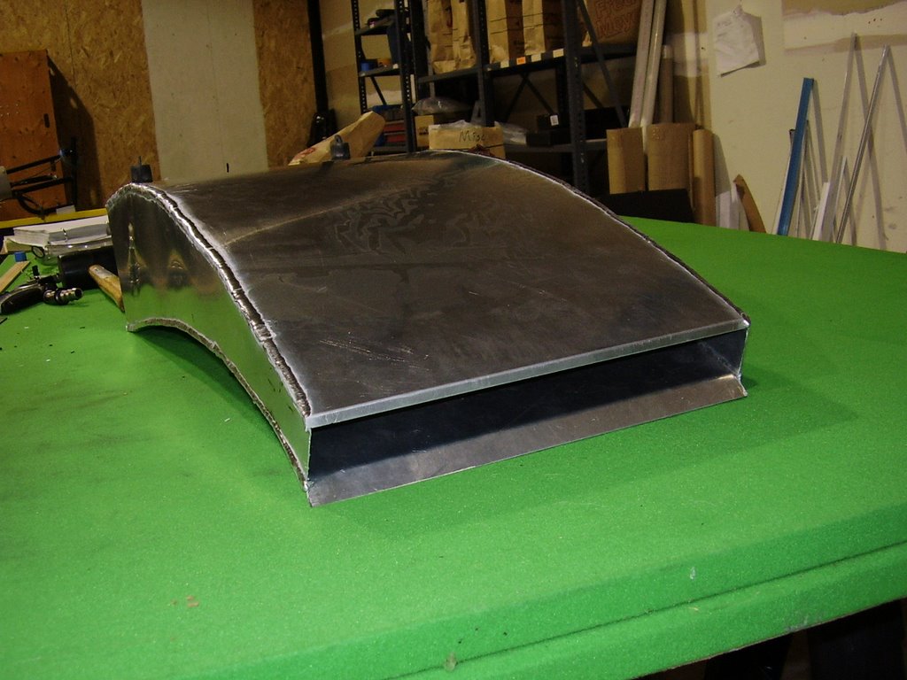
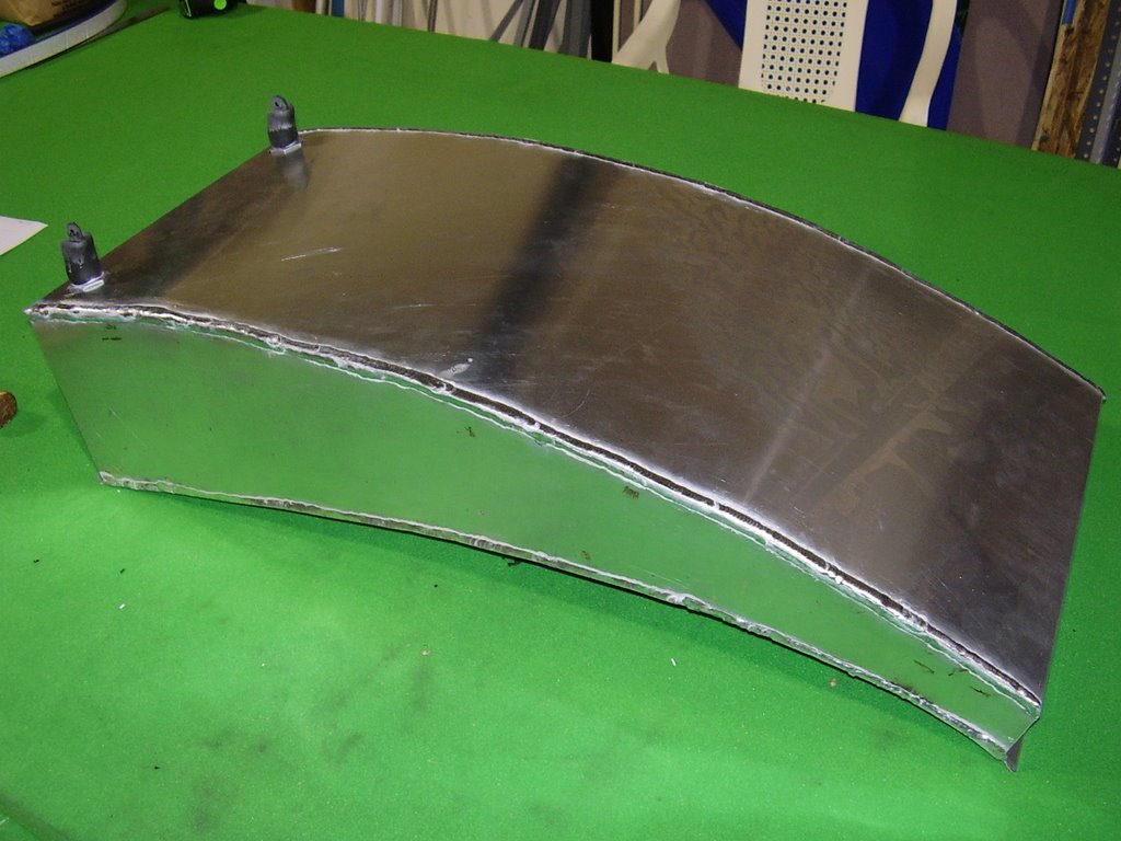
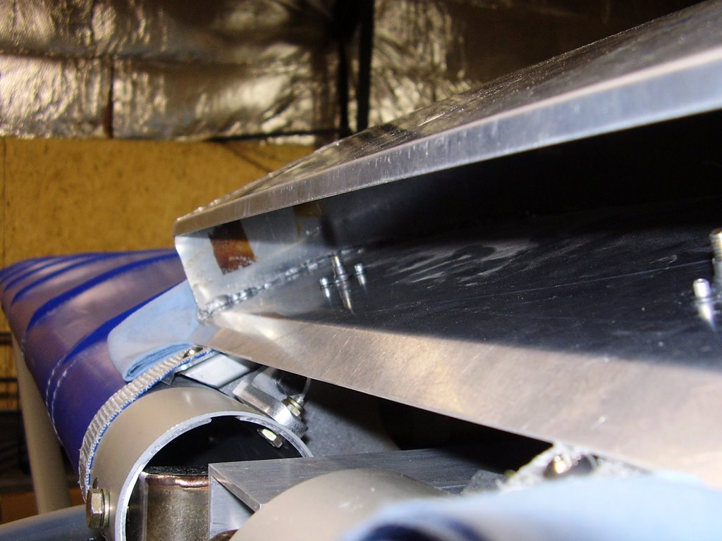
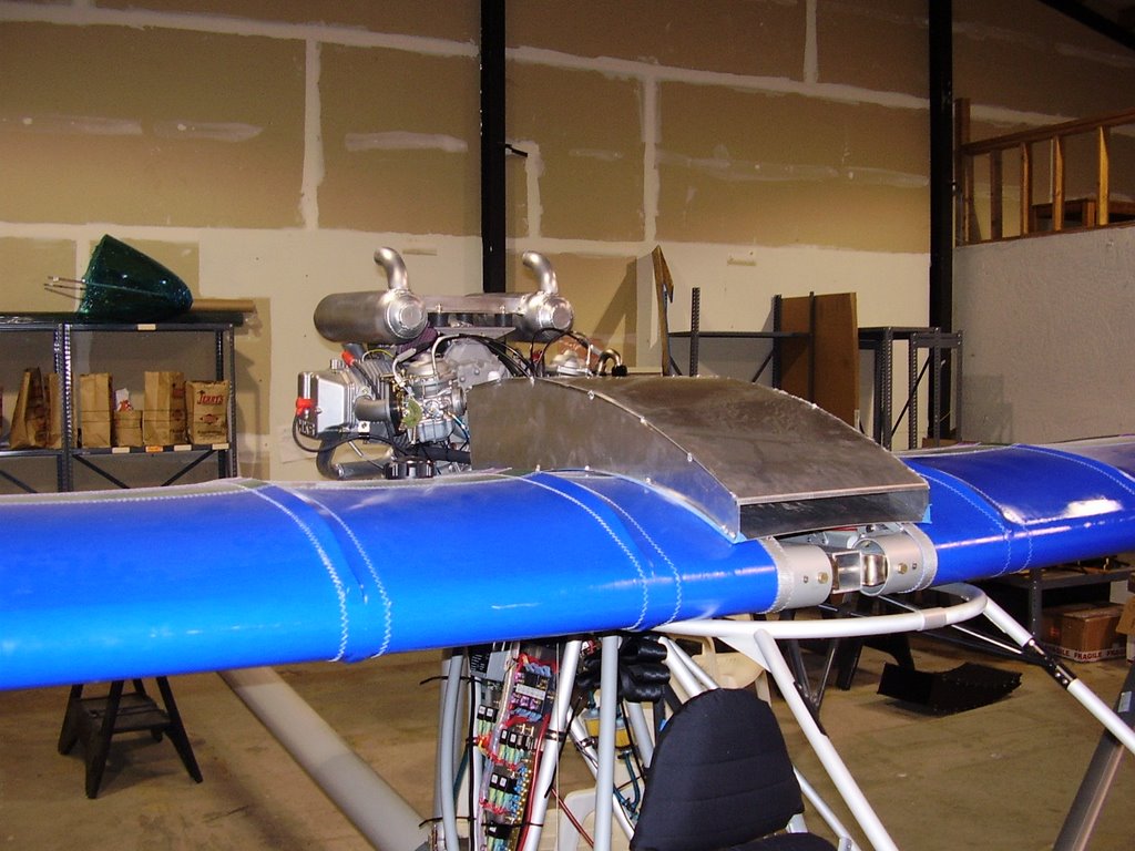
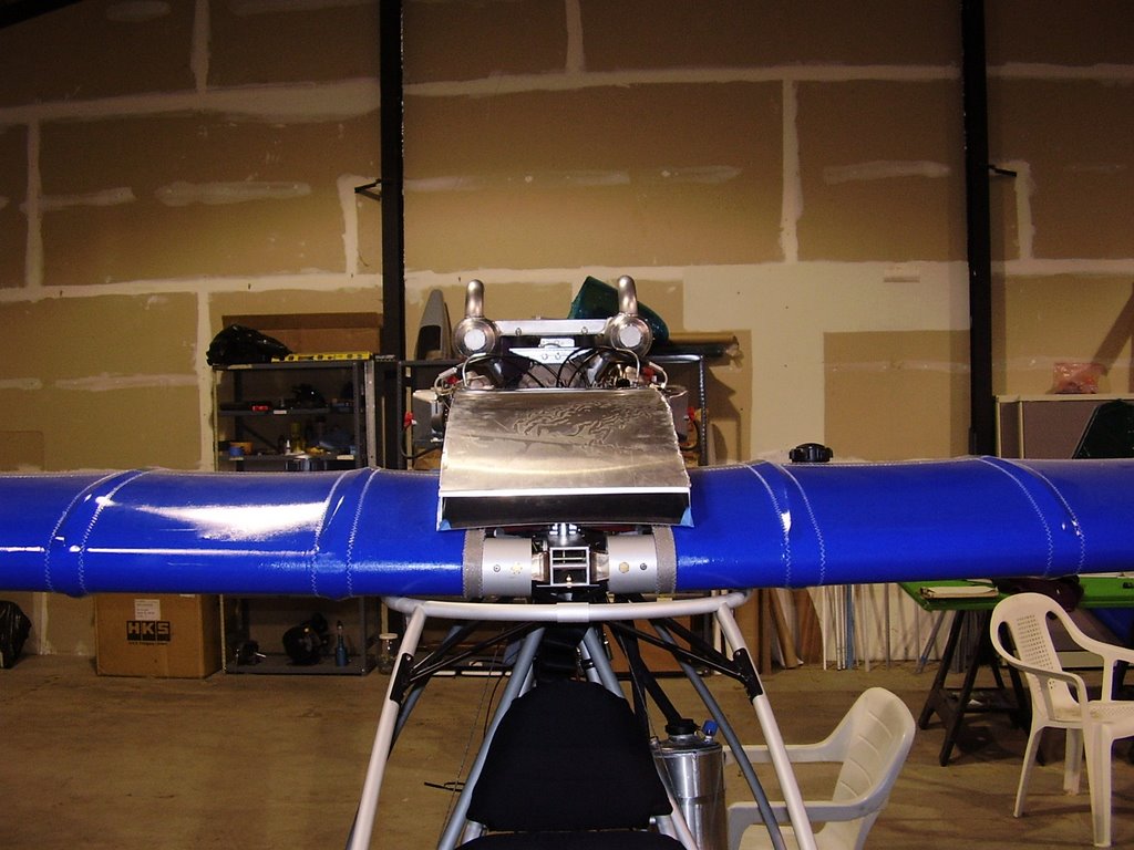
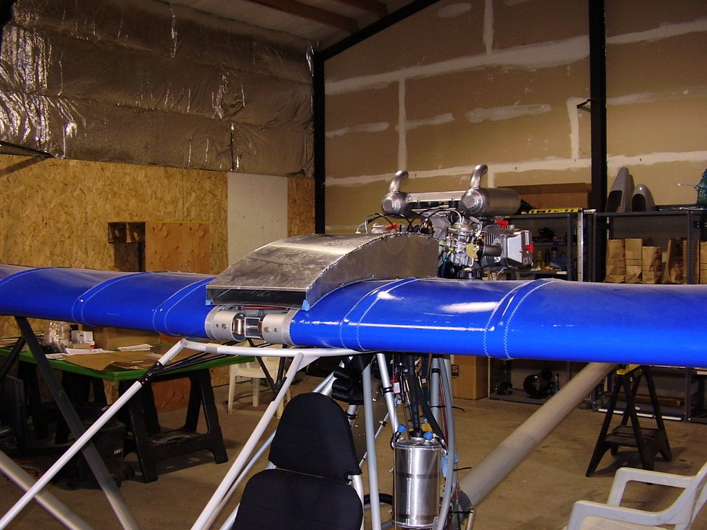
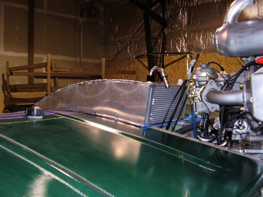
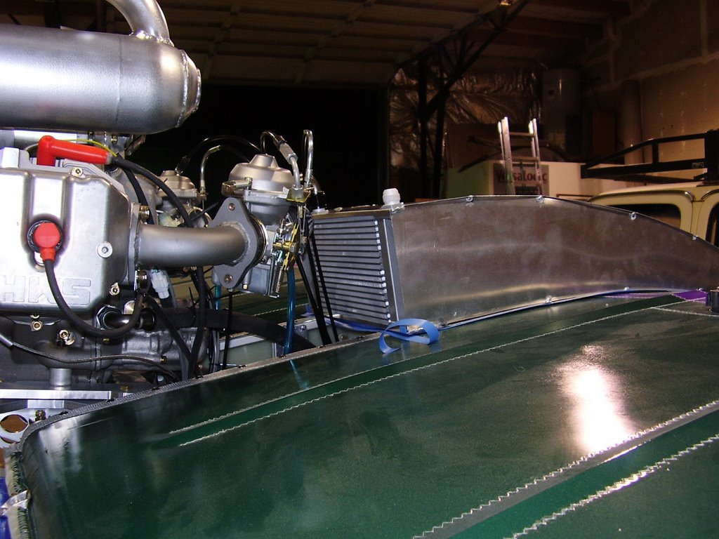
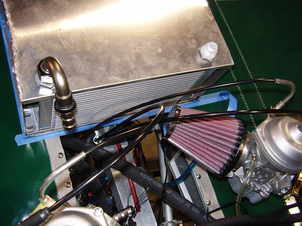
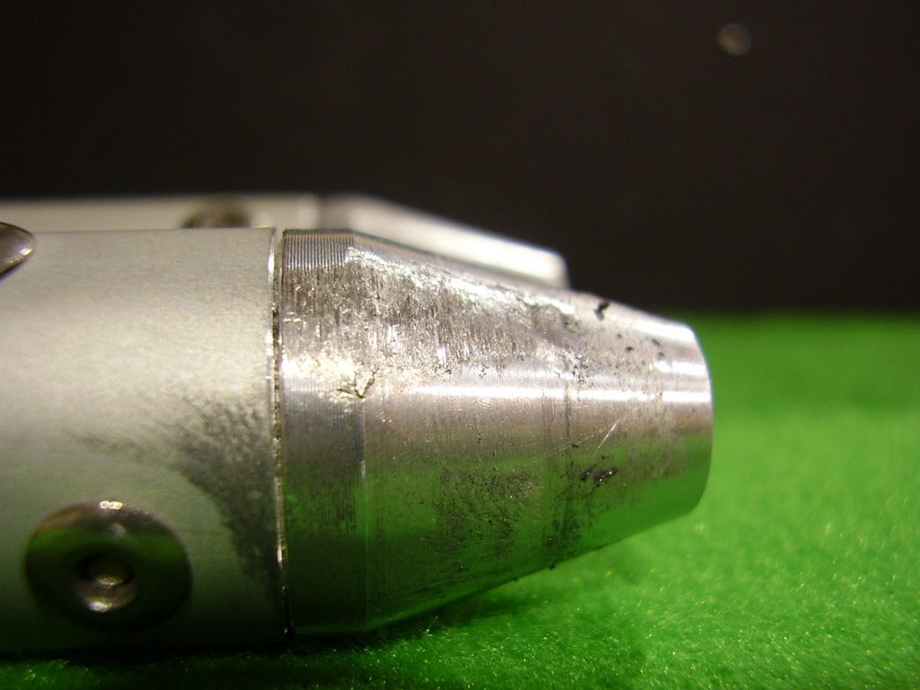
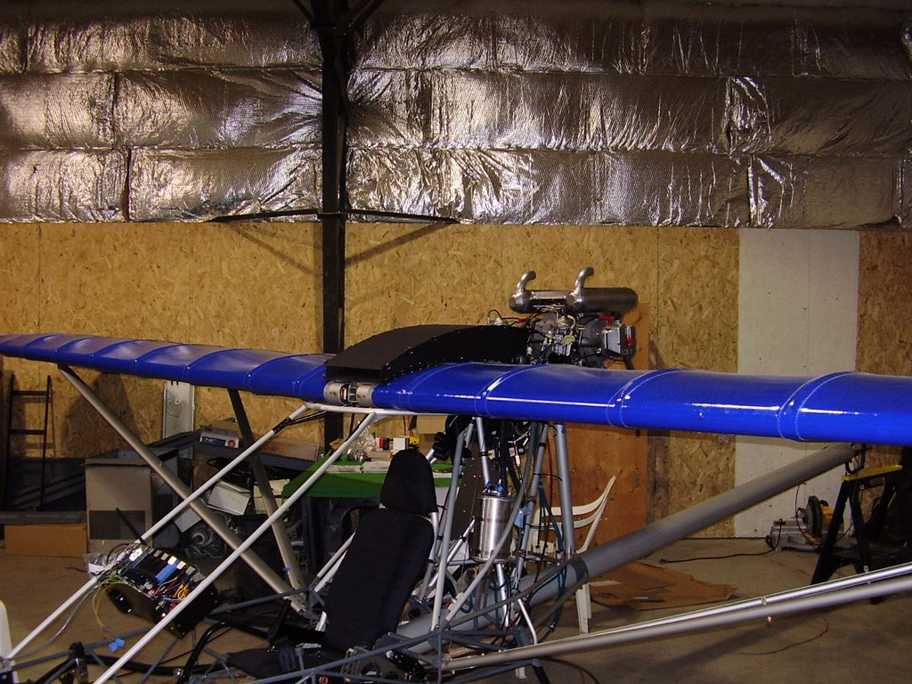
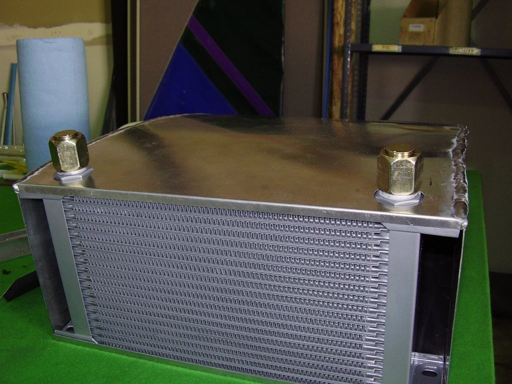
Below are some pictures of my cowling. The cowling is not completed yet, it still needs some more welding done to it. Only one seam is complete; the others are only tack welded.

There have been a few design changes since my last posting for the cowling. Instead of riveting the cowling together, I am having it welded together. Another design change was the lack of hems on the leading and trailing edges. The 6061-T6 material is too brittle to allow for the 180 degree bends. Instead I had 90 degree bends placed on the trailing edges and a 60 degree bend placed on the top leading edge. The bottom leading edge was left straight.

The opportunity to have the cowl welded kind of fell into my lap. The welder is a friend of a friend who has a TIG welder in his garage. He was willing to weld the pieces together for relatively cheap. It was thought that welding would be easier and quicker than cutting, bending, and riveting all of the tabs. Unfortunately, the welding is not going as smoothly as we (me and the welder) had hoped.

We tried tack welding the pieces together without creating a complete jig. The pieces held their shape while they were cold and held together with tape but when heated during the welding processes, they would distort. Clamping the pieces didn't help either since it only provided a local force. The metal would become soft during the welding and would warp around the clamp.

The top and bottom pieces started to pull away from the side pieces when heated during the tack welding process. This caused a gap to form and a small distortion to form at the start and stop points of the tack welds on the top and bottom pieces. This distortion will probably not be an issue once the seam is completely welded since the edge of the material is consumed into the bead of the weld.

The various width gap between the pieces made the welding very difficult which made it impossible to created a "pretty" bead. You can see in the photos that the weld is very rough.

It appears that the pieces didn't expand the same amount under the heat of welding. You can see in the picture that the side piece became wavy. The curvature of the top piece probably allowed it to absorb the heat expansion all in the outward direction. Since the side pieces were tacked together, they were forced to bow both inwards and outwards. In hind sight, it would probably have been better not to tack the pieces together. One continuous bead would allow the metal to expand freely. This would allow the material to stay straight for the first weld on either of the sides but the second weld may see the same type of expansion problems.

Another theory is that the aluminum pieces don't expand uniformly. The aluminum could expand differently along the grain versus against the grain. The top piece has its grain running front to back, the sides run top to bottom.

Another problem is the bottom leading edge isn't holding the shape of the curved sides. You can see in the photos that the edge is curved upwards in the middle. The other seams are doing fine since they have bends which give them extra strength. I considered having top and bottom pieces rolled to give them their curve but decided against it since the bottom curve doesn't have a constant radius because of the airfoil shape. I will try to give the metal a slight bend or crease by hand to help it hold it's shape.





Friday, August 18, 2006

Rubbing Aileron Push/Pull Tubes - 1.5 hours (321.5 Total)

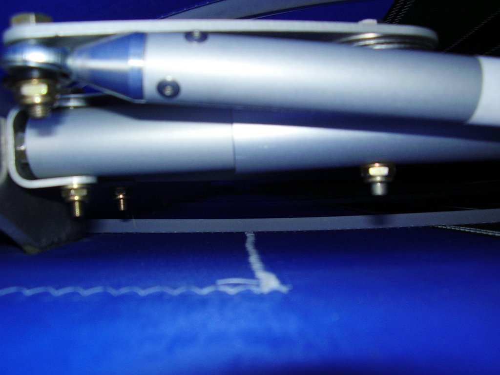
A while back I noticed that the Short Push/Pull Tubes for the ailerons were binding up on the Bell Cranks inside the wings when the ailerons were fully deflected. This binding was reducing the aileron range of motion from 45 degrees to 35 degrees, 5 degrees on each side.

To alleviate this I needed to add a 1/4" Plastic Washer (PW-4) and a 1/4" Thick Washer (AN960-416) between the Bell Crank and the Male Rod End in each wing. Rans recommended that I use 1/4" Zinc Plated Washers (KSHW0075) instead of the 1/4" Plastic Washers. They also suggested I replace the existing 1/4" Plastic Washers that are between the Male Rod End and the lock nut. I also needed to replace the 1/4" Bolt (AN4-7A) with a longer 1/4" Bolt (AN4-10A) to handle two new washers.

With the above fixes, the binding was completely eliminated. Now when the ailerons are fully deflected, there is a distinctive stop instead of a binding/grinding feeling. This stop is caused by the Long Push/Pull Tubes hitting the same Bell Cranks within the wing.

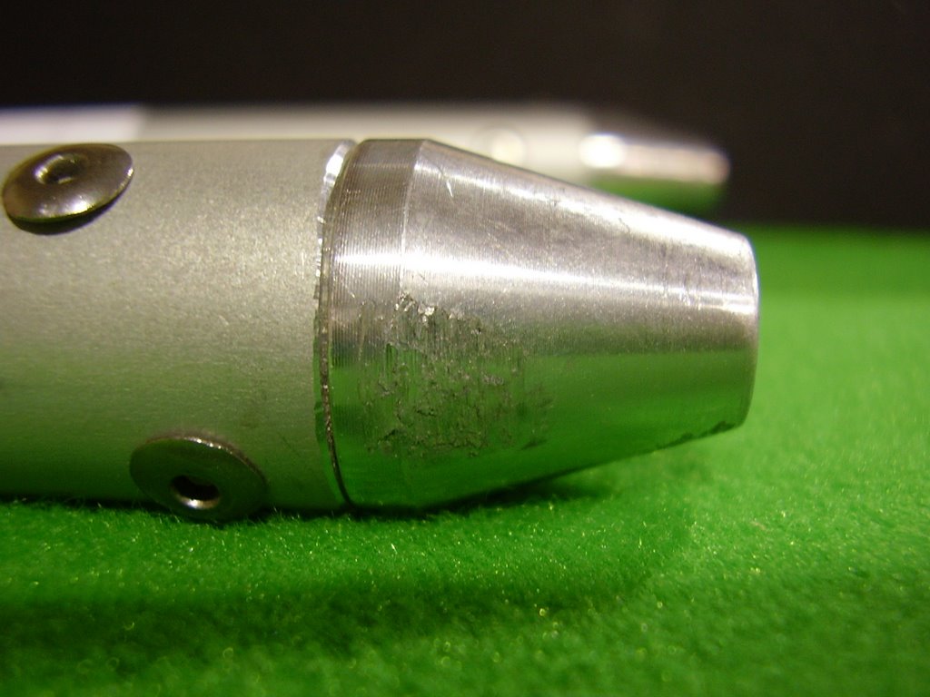
Below are some pictures of the damage that was being done to the Short Push/Pull tubes from the binding. The last picture was taken from inside the wing to try and get a clear view of the binding prior to the fix. Implementing the fix through the zippered portal wasn't as hard as I had thought it would have been. Removing the Short Push/Pull tube was necessary along with taping the 7/16" wrench to a yard stick to hold the bolt head.


Wednesday, August 16, 2006

More Cowl Mockup - 3 hours (320 Total)

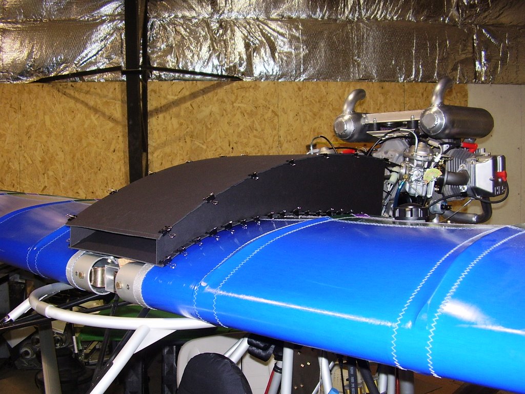
Below are some pictures of a more complete mockup of the oil cooler cowl. In the pictures, the two side pieces are reversed to allow for the pieces to be held together with binding clips.

I intend to make the cowl out of 0.032" 6061-T6 aluminum sheeting. The side pieces will have metal tabs that will be folded over to allow for riveting. A 19 row oil cooler will be mounted in the back of the cowl. The leading and trailing edges will have hems folded into them to give them extra strength.


Labels - 1 hour (317 Total)

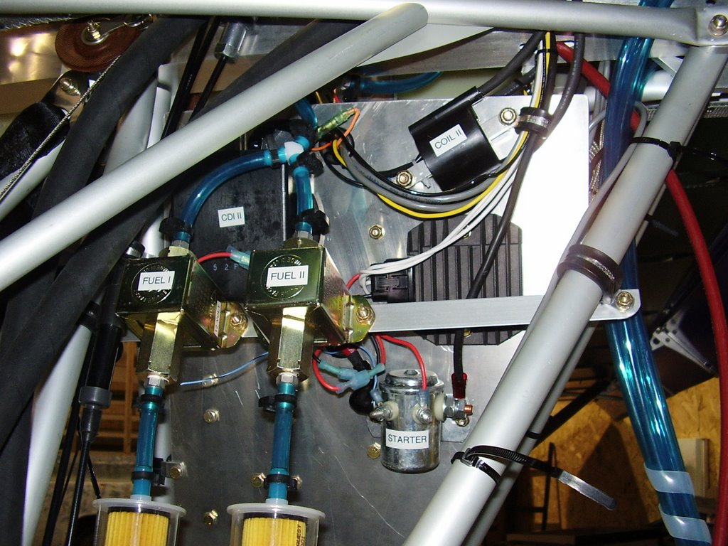
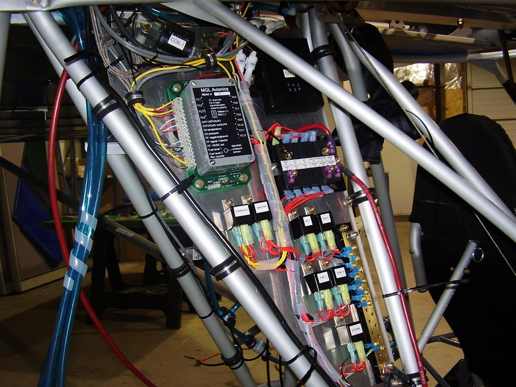
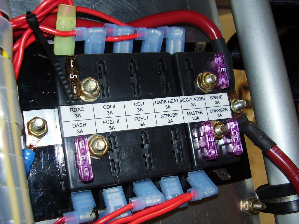
Today I created labels for the major components of the electrical system. I also created labels for the two fuse blocks.


Saturday, August 12, 2006

Instrument Pod - 4.5 hours (316 Total)

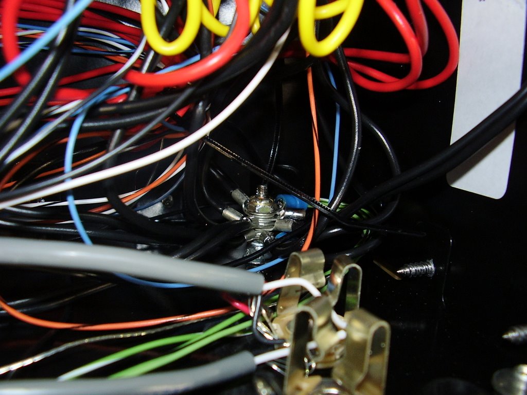
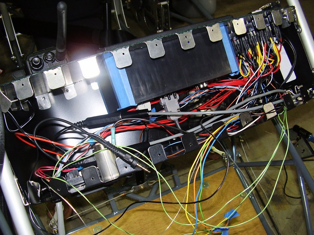
Today I did some more work on the instrument pod. First I reinstalled all of the switches and wiring. I then added a bolt to act as a ground point; this should be more reliable than using the terminal of the master switch which I was using before.

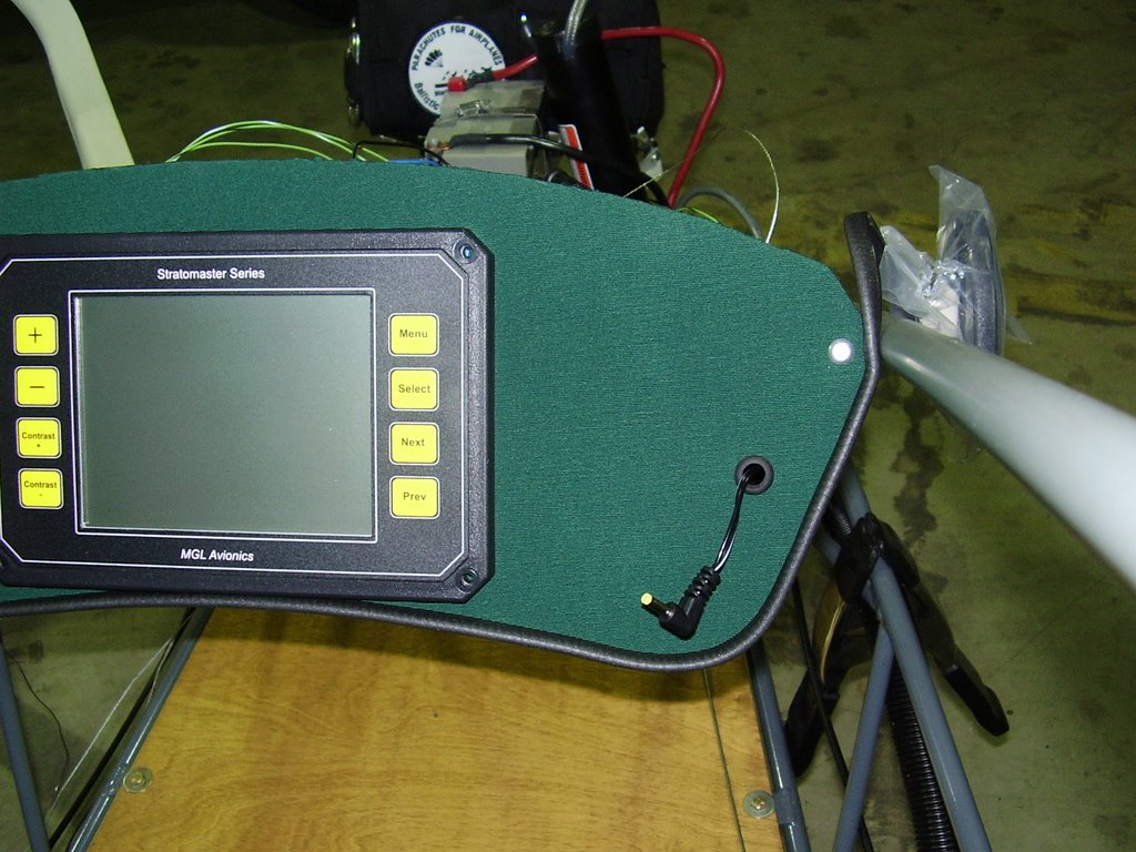
I also added cables for my radio; one for external power and one mic/phone extension.

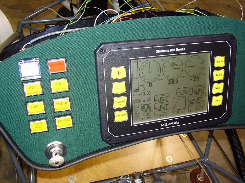
Lastly, I created labels for the push button switches on the dash.


Above you can see the ground bolt and wiring for the mic and headset connectors.


Above you can (just barely) see the labels for the push button switches.


Above is the wire and connector to power the radio.


Thursday, August 10, 2006

Wing End Caps - 0.5 hours (311.5 Total)

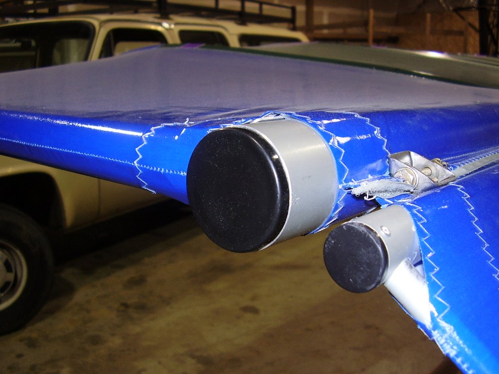
Today I installed the end caps for the wings. (Since I'm sitting around waiting for oil cooler parts to arrive, I am working on little things)

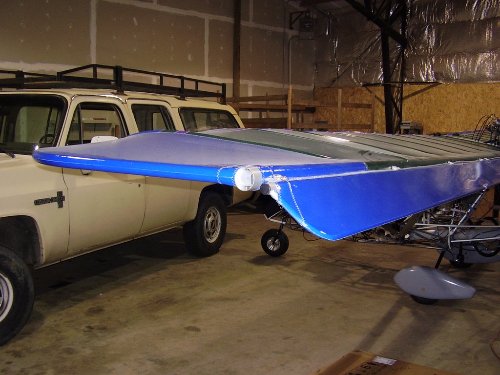
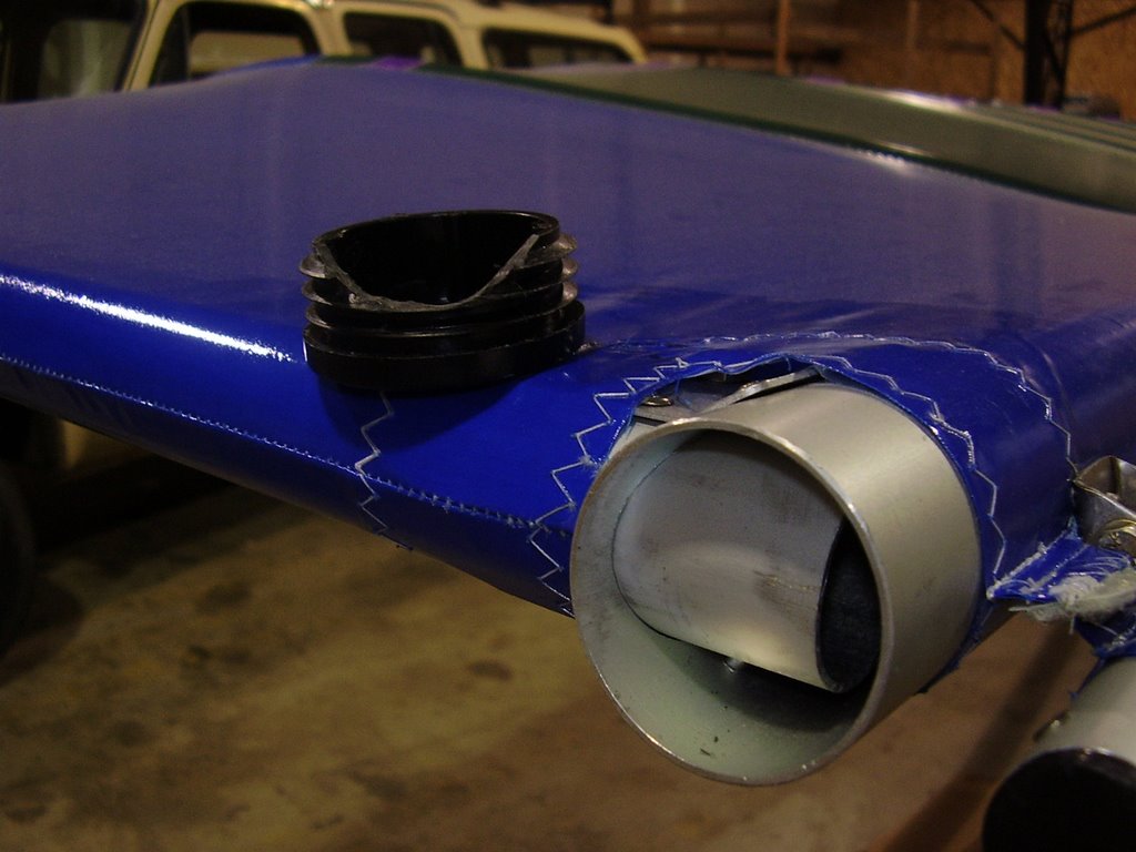
These caps were easy to install, they simply pushed into the trailing edge spare aluminum tubing. I did need to notch the caps to accommodate the aluminum tube from the rounded wing tips. This was easily done with my Dremel tool.


Wednesday, August 09, 2006

Cowl Mockup- 1 hours (311 Total)

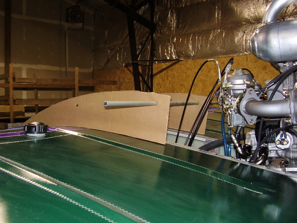
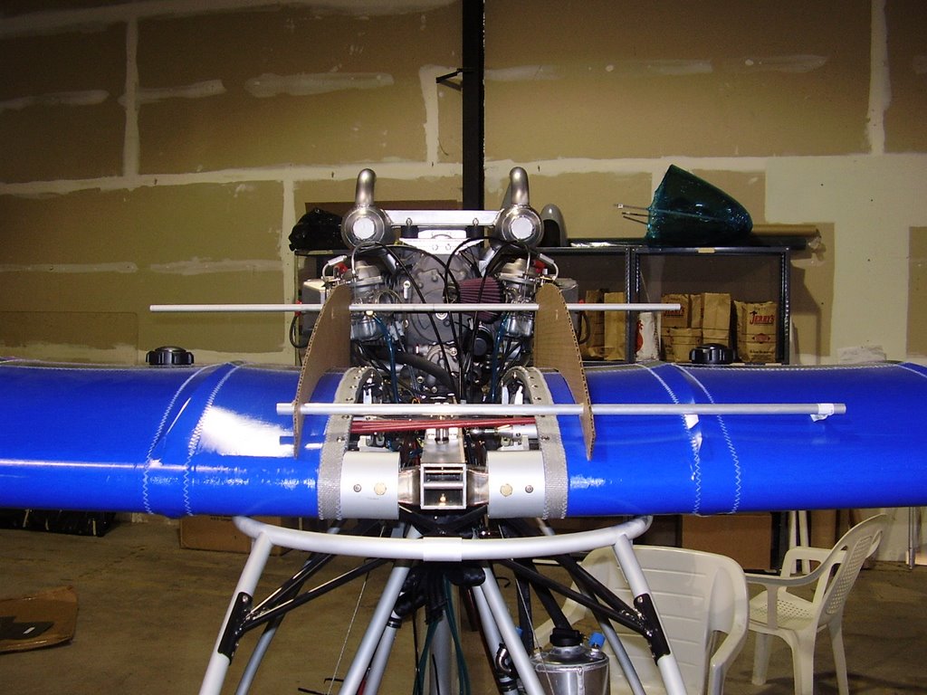
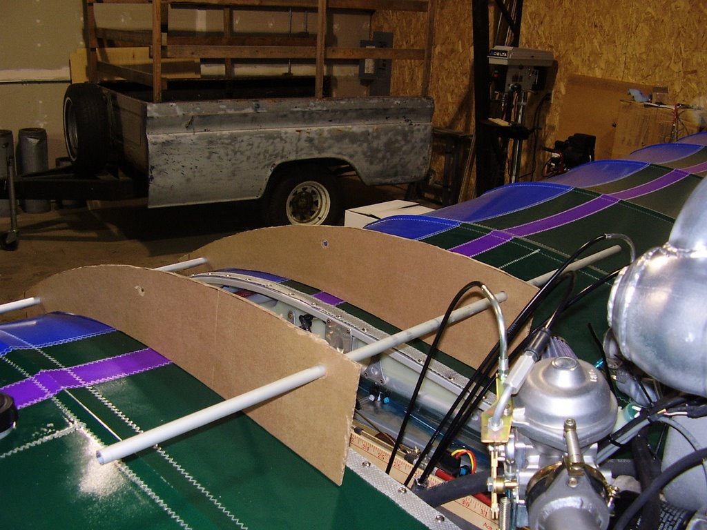
Here are some pictures of a cardboard mockup of the cowl I plan to build for my oil cooler. The 19 row Mocal oil cooler will fit flush inside the back end of the cowl. The oil fittings will protrude out the top of the cowl to allow for removal. The cowl will have both top and bottom surfaces. The cowl will be fastened to the both wing roots with Camloc fasteners.

The front opening of the cowl is right above the leading edge of the wing to allow it to collect high pressure air. The opening will be 2" tall by 13" wide.

This setup for the cowl and oil cooler does not leave much room for the thermostat which I was planning to install. The oil line routing without the thermostat would be straight forward. I will do some more research to see if running without it would be recommended.


Tuesday, August 08, 2006

Fuel Lines - 1 hours (310 Total)

Today I rerouted the fuel line that runs to the fuel pressure gauge with some 90 degree fittings. This prevents the fuel line from rubbing against the wing root.

I also placed fuel line clamps on all of the fuel lines that still needed them. I had ran out and needed to purchase more.


Tuesday, July 25, 2006

Instrument Pod - 3 hours (309 Total)

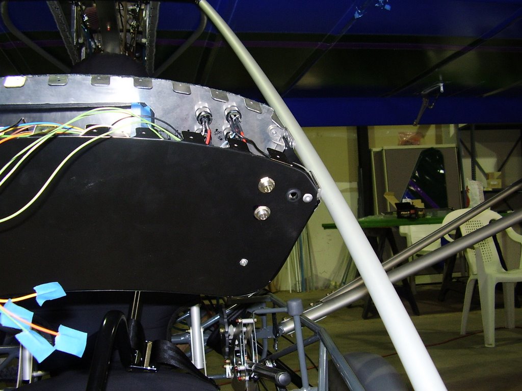
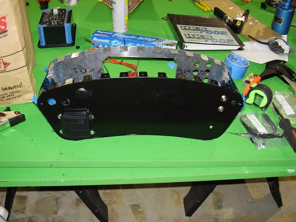
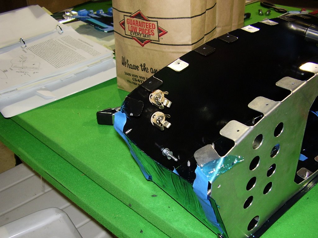
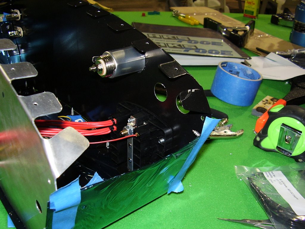
Today I did the final assembly of the instrument pod and mounted it to the inside of the plane.

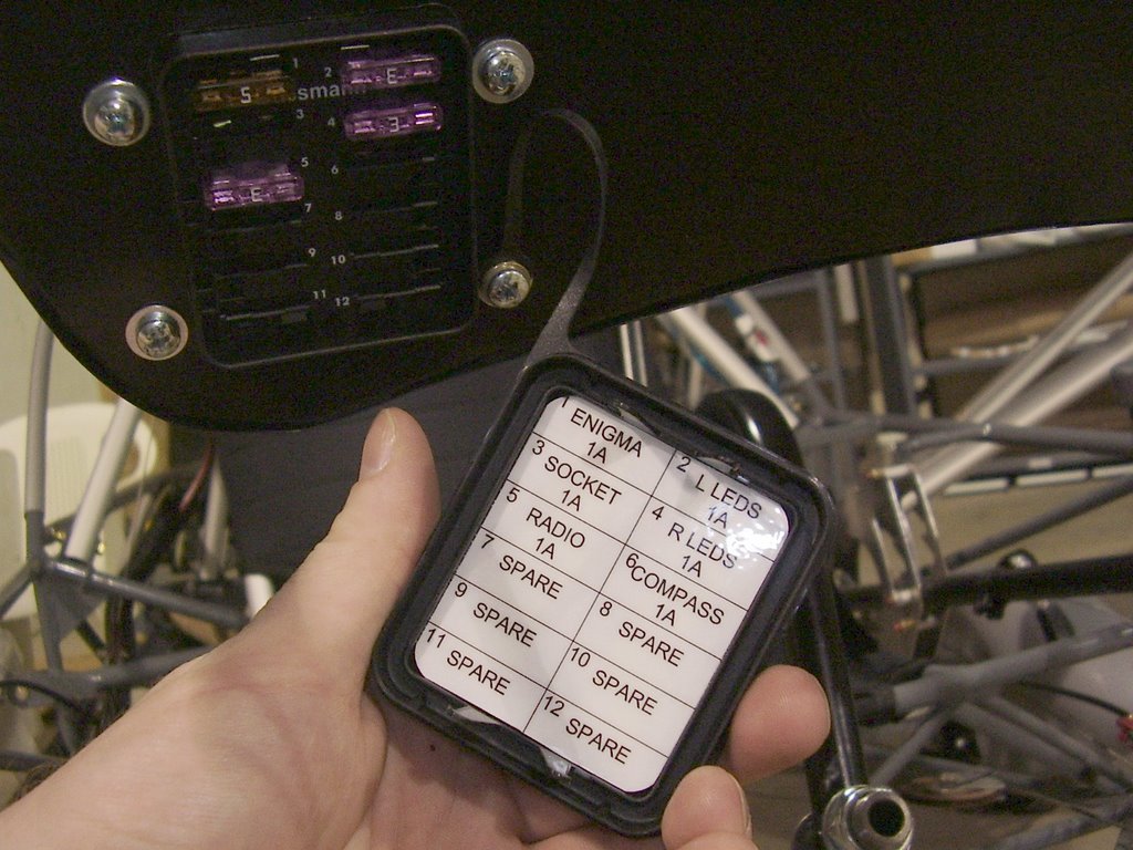
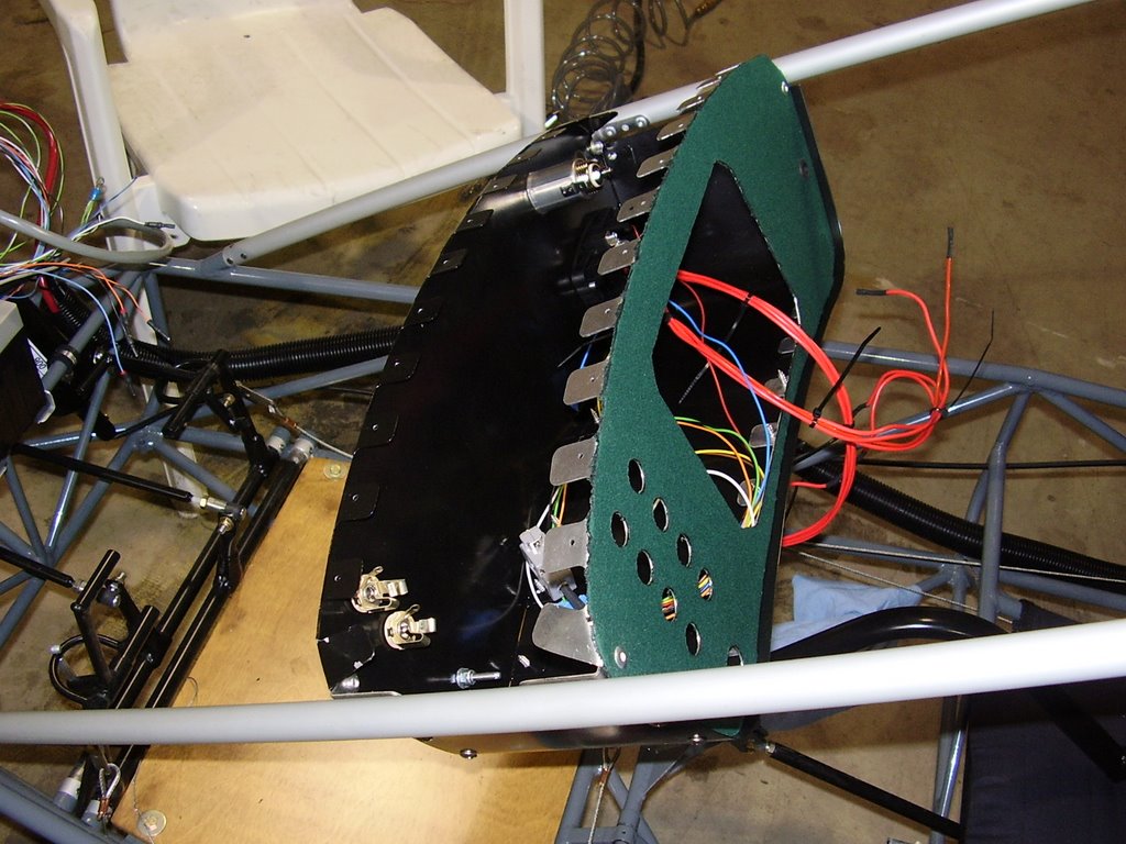
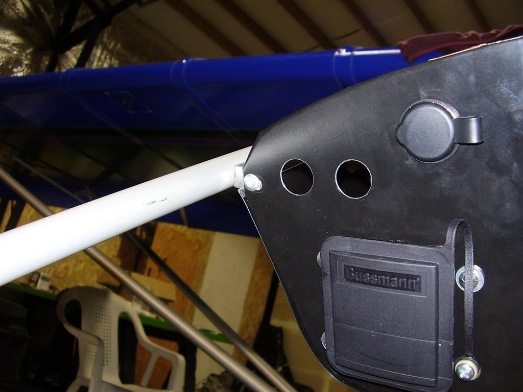
In the three pictures below you can see the mounting of the fuse block, cigarette lighter, and head phone and speaker jacks.


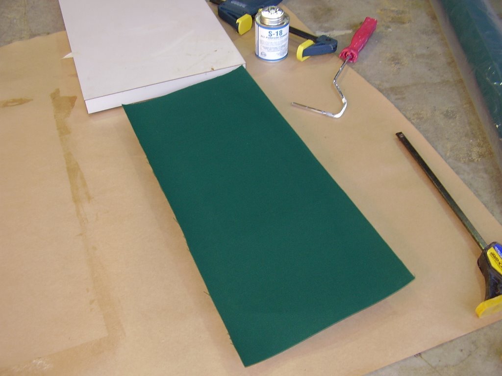
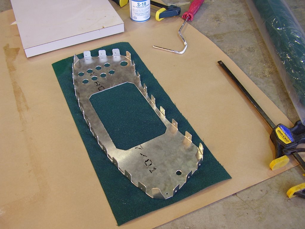
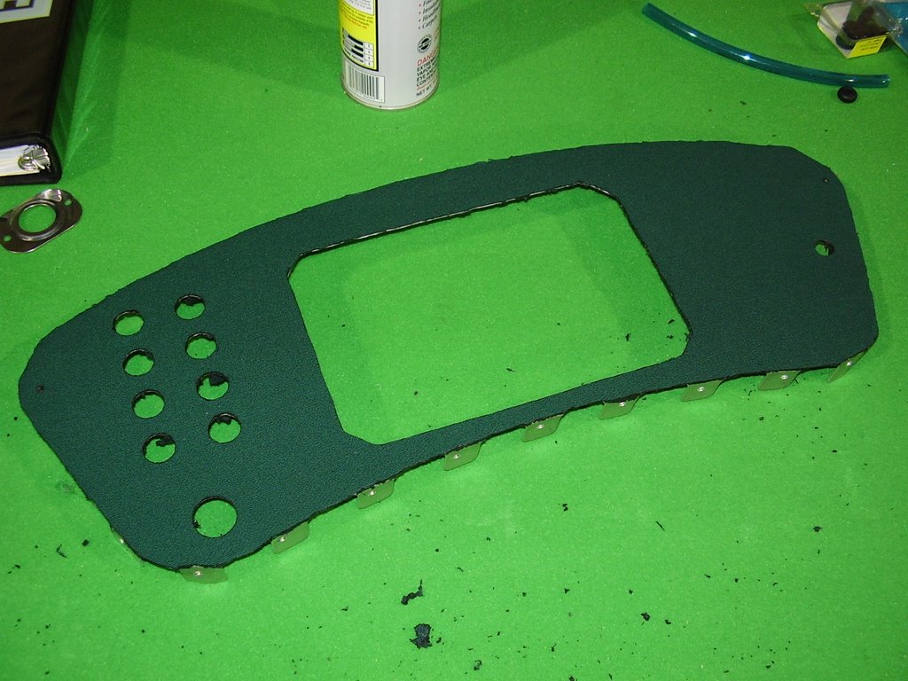
In the two pictures below you can see how I glued my interior fabric to the instrument panel. I used a heavy duty role on glue which is water proof and heat resistant. I chose a synthetic canvas type fabric for the plane's interior. This fabric is intended for exterior canopies and is sun and mildew proof.


After a few hours and the glue had set, I started cutting away the excess material with a soldering iron.


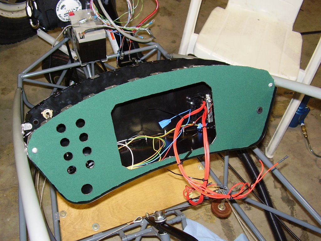
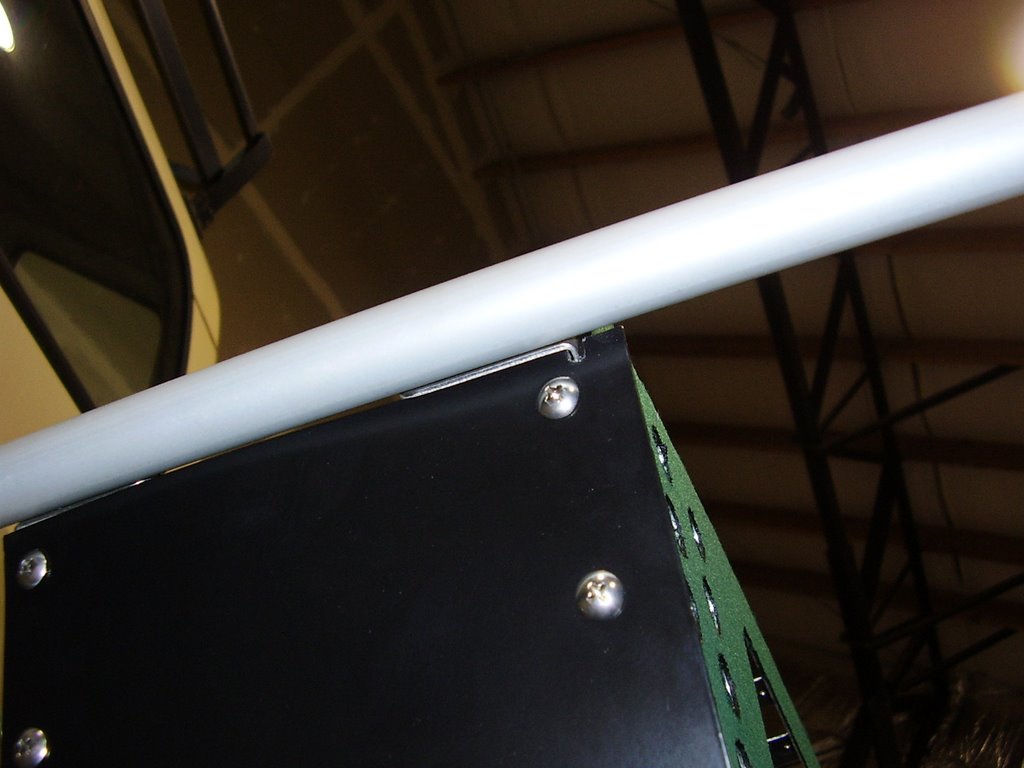
I then reattach the instrument panel to the bottom panel and proceeded to secure the instrument pod into the airplane.


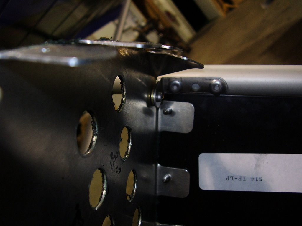
I needed to use my Dremel Tool to notch out one of the corners to allow the bottom panel to fit around one of the brackets that holds the pod in place.


I also needed to reposition one of the rear holes to allow for a secure fit.


And lastly, I needed to add washers between the brackets and back panel to allow for proper alignment.

Monday, July 24, 2006

Wing Fuel Lines - 4 hours (306 Total)

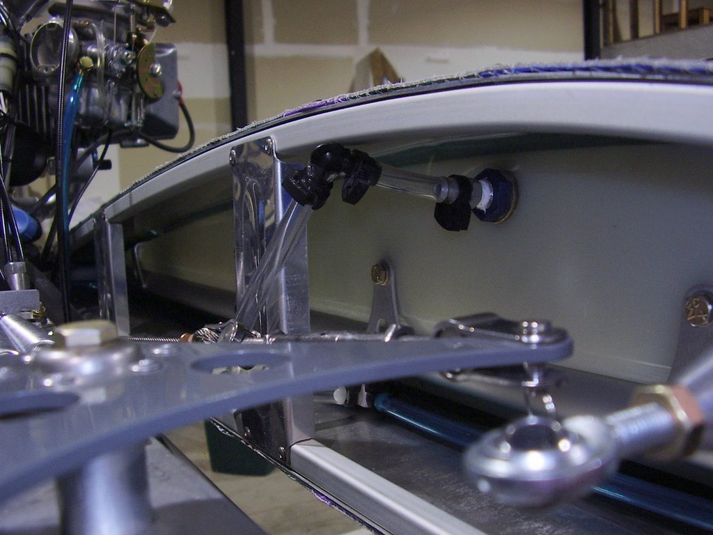
Today I routed the fuel lines from the wing tanks to the fuel bracket. This included creating the site gauges to allow me to see the fuel level in the tanks.


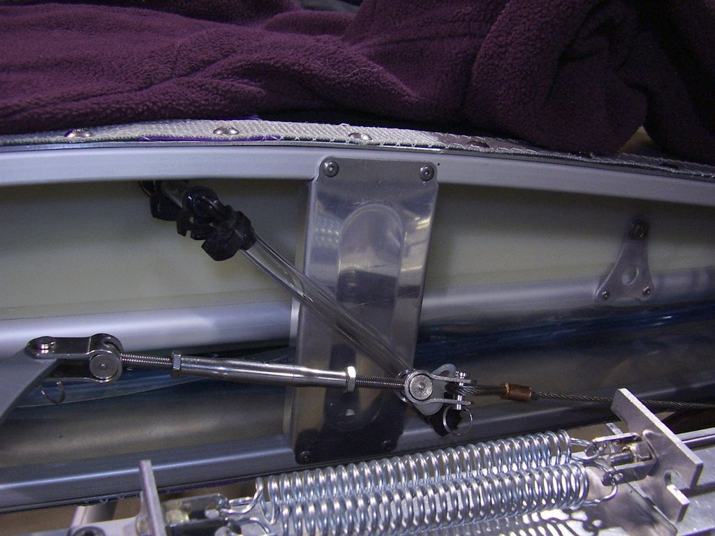
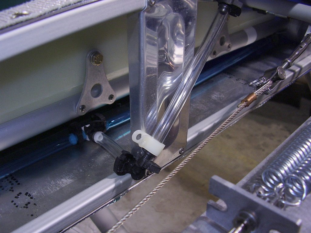
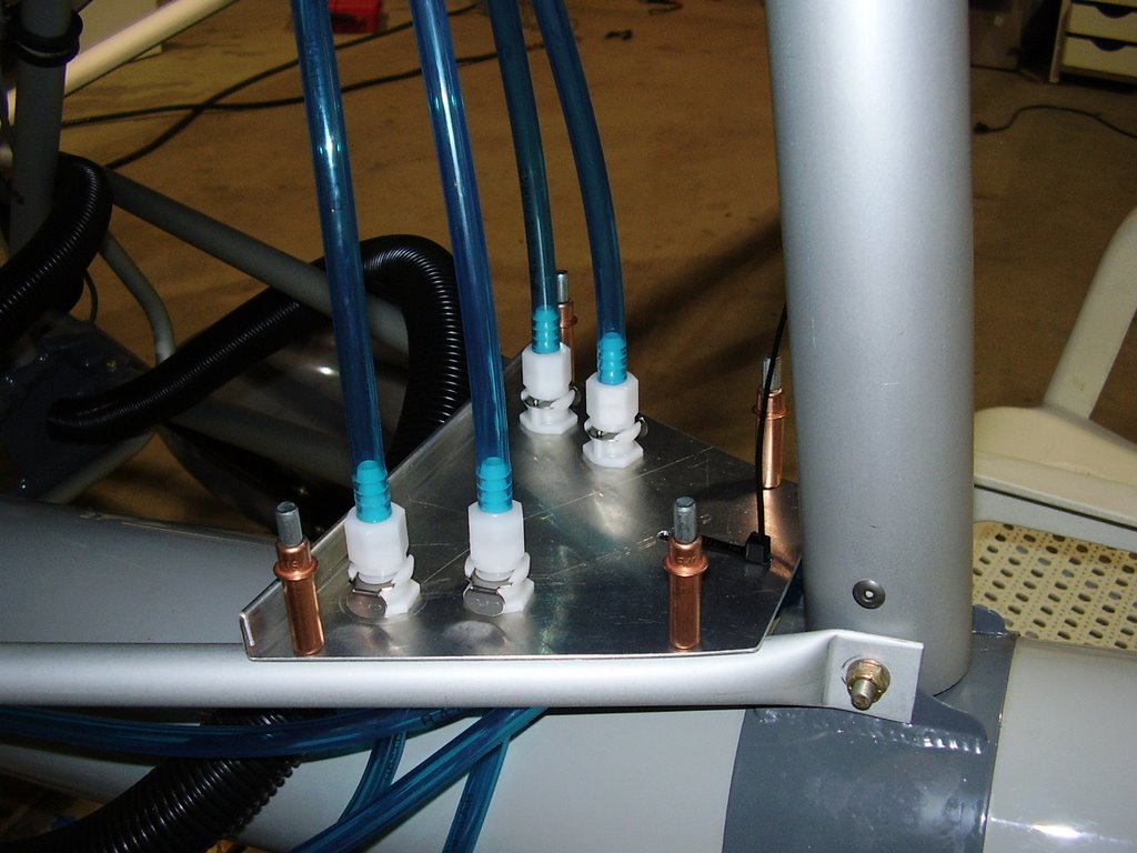
In the picture above you can see a white plastic bracket that is yet to be connected. I was unable to drill the hole or screw in the bracket because of the small amount of room between the wing and the root tube. I will need to connect this when I take the wings off.


When I reconnect the wings prior to flight, I will add a cushioned hose clamp to secure the fuel lines to the engine mount bolts.