Wednesday, April 05, 2006

Parachute Bracket- 6 hours (224 Total)

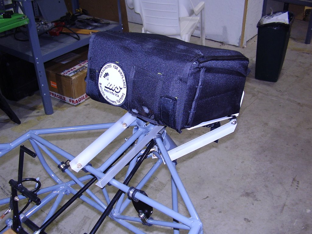
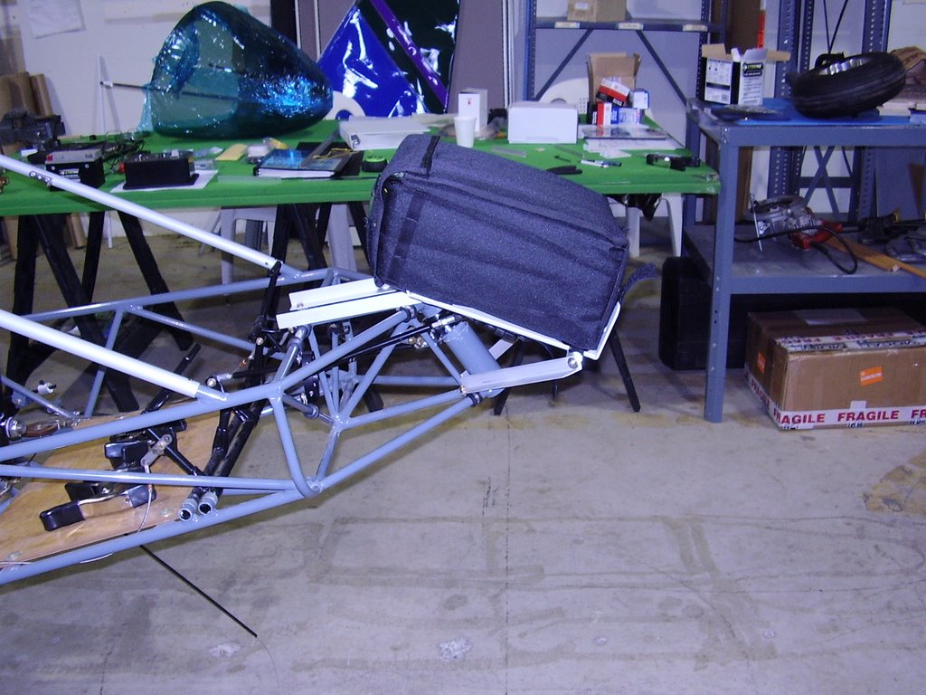
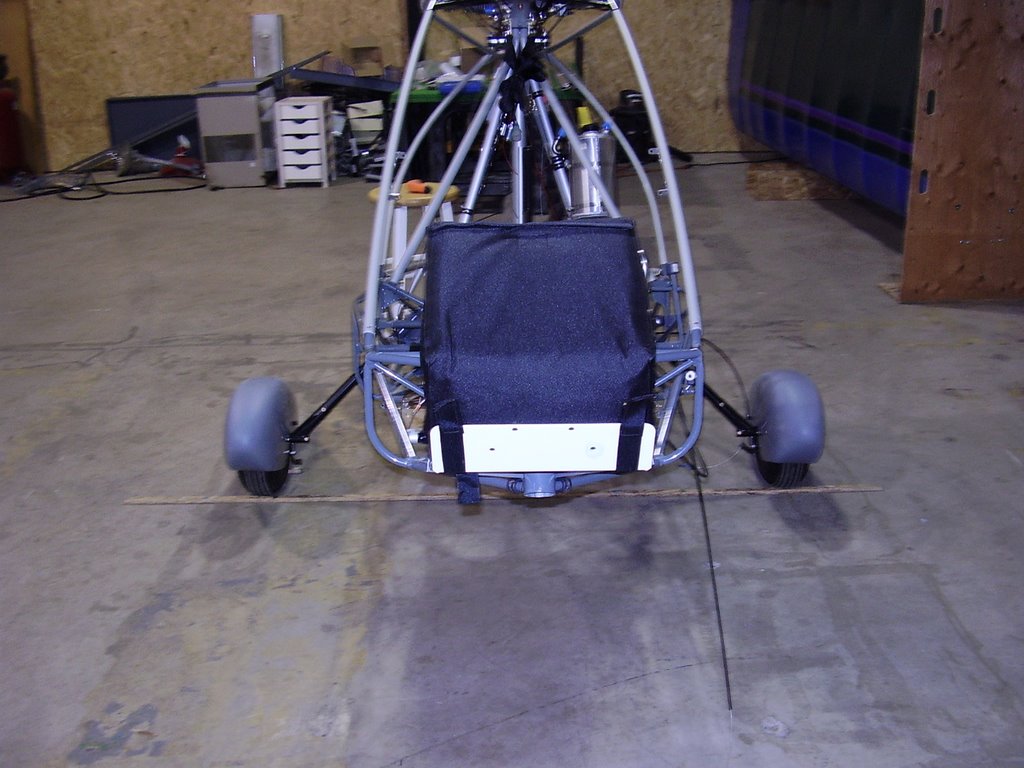
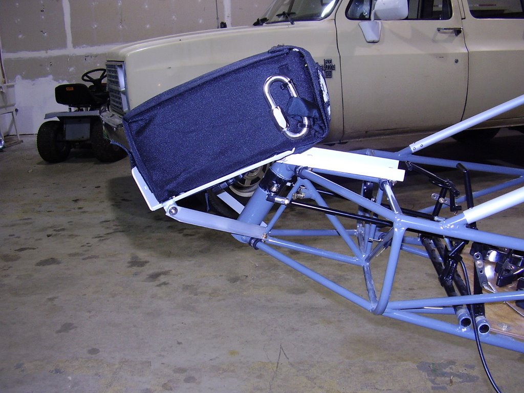
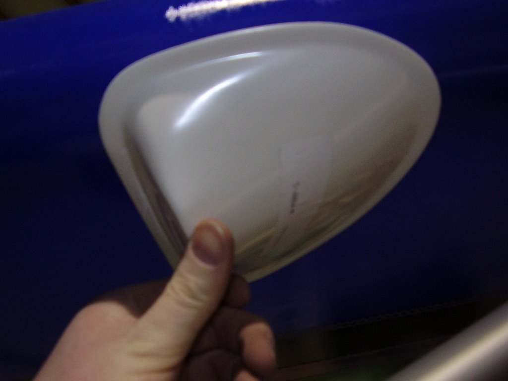
Figuring out how to mounting the parachute in the nose was a difficult task. Because the S-14 Long Wing is so tail heavy to begin with, adding the 15 extra pounds of HKS engine caused the center of gravity to be very far back. With my estimated CG calculations, I would be right at the edge of the CG window if I placed the parachute in the rear of the fuselage. Moving the parachute to the nose of the plane moves my CG forward by almost 2.5 inches.

My other goal with the parachute mount was to create a location that the battery would be able to sit.

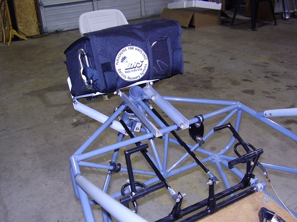
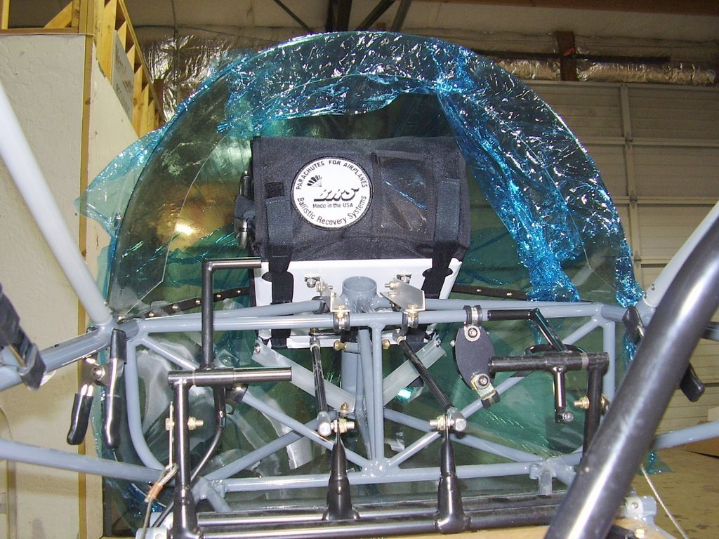
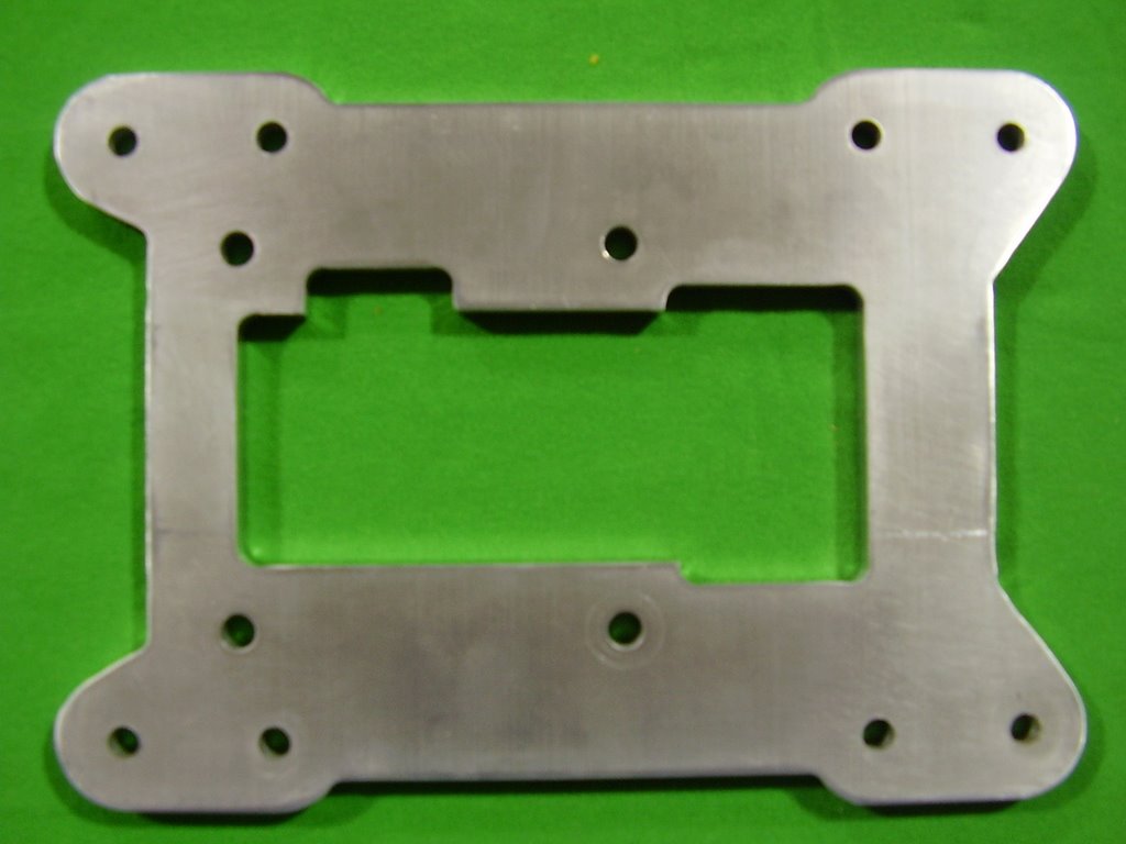
I used the BRS supplied plate as a starting point. I jerry-rigged the plate to correct location while I dry fitted the nose cone into place.

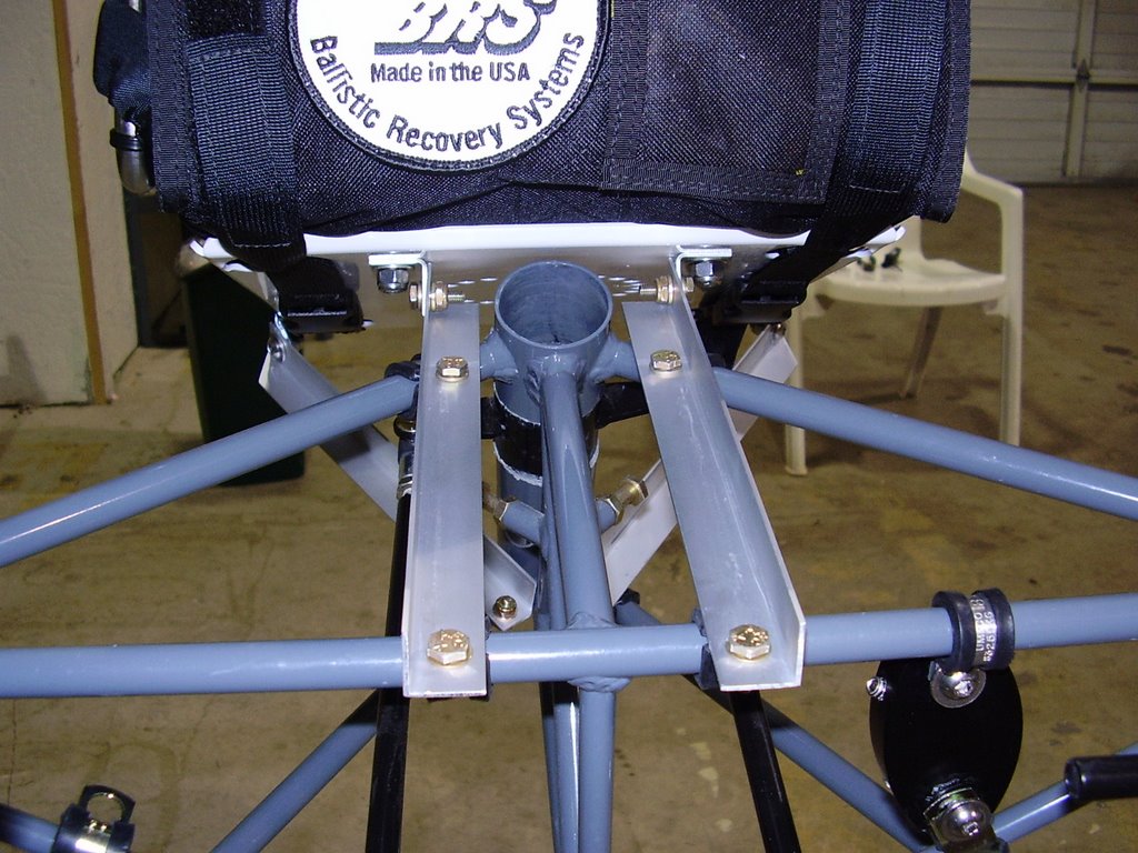
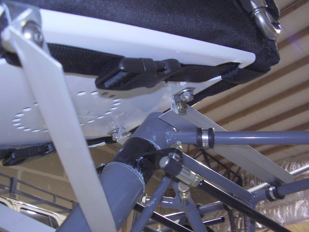
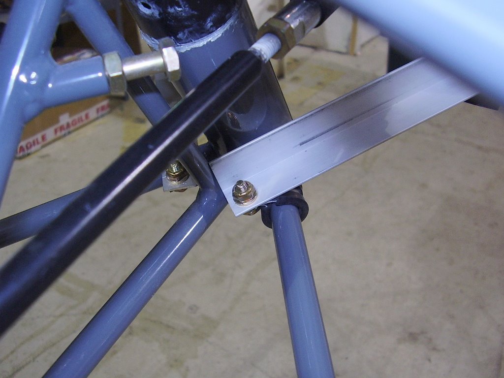
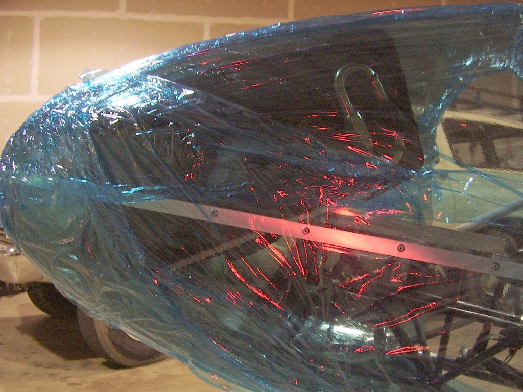
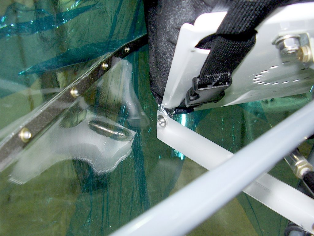
Once I had the right location for the plate, I drilled two holes into the plate to accommodate two 90 degree brackets that would connect to two pieces of 3/4" x 3/4" aluminum angle. These two pieces of angle aluminum are the top pieces you see in the pictures. They are spaced such that my battery will sit inside of the frame they create.

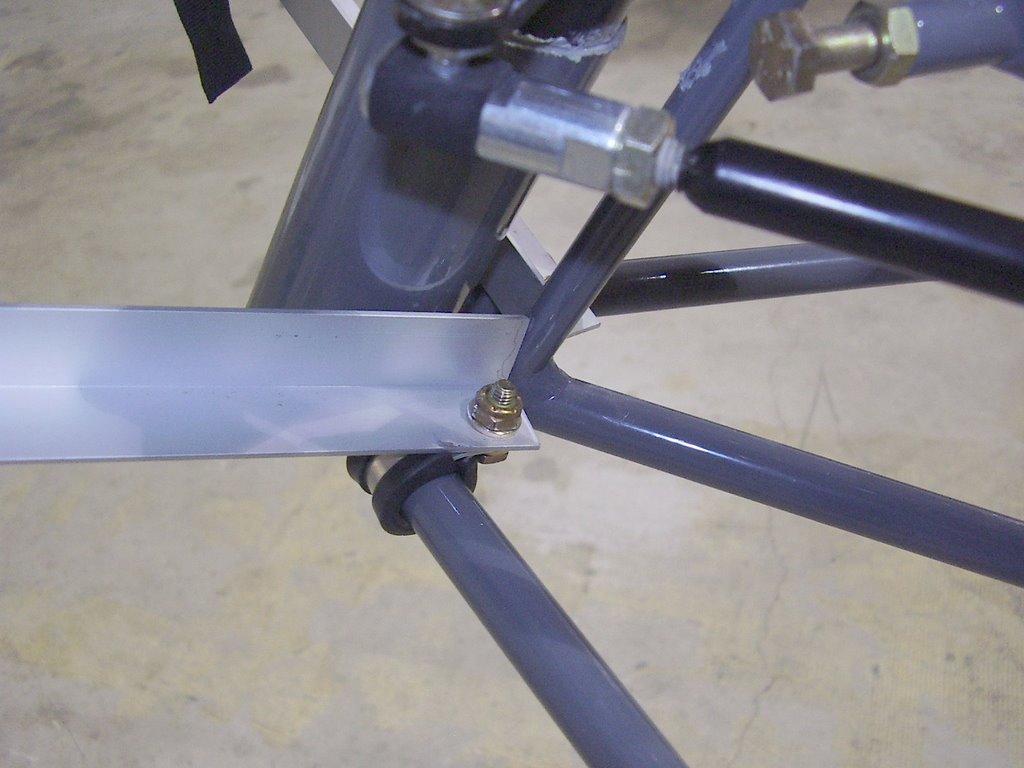
The two lower pieces of aluminum angle keep the plate from rotating around the brackets. These pieces are connected to the plate with two metal pipe/wire brackets that have be deformed to grip the at an odd angle. The other ends of the aluminum angel is connected to the planes frame with similar, but not deformed, metal pipe/wire brackets.









Monday, April 03, 2006

Fuel Filter Brackets - 3 hours (218 Total)

I spent a lot of time researching the correct fuel filter to use. I came up with the 33001 filter from Wix. These filters are sold by Carquest under the 86001 part number. They are rated at 12 microns.

The HKS manual states to use a 15 micron or less, mesh type filter. Unfortunately, most filters and their suppliers don't state the filter's micron rating.

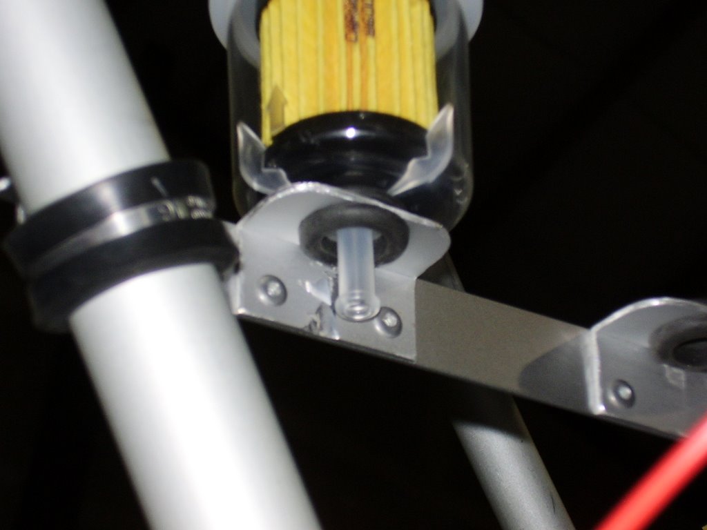
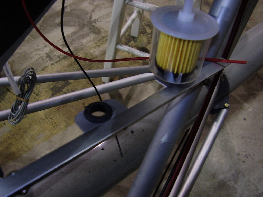
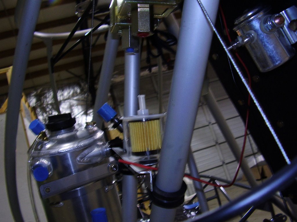
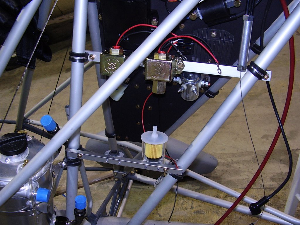
I spent several hours creating mounting brackets that would hold the fuel filters. I use some 3/4" x 1/2" aluminum angle which I drilled a 5/8 inch hole in. The hole accommodates a rubber grommet that holds the filter nicely.


Sunday, April 02, 2006

Oil Pressure Sender - 1 hour (215 Total)

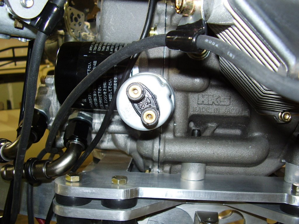
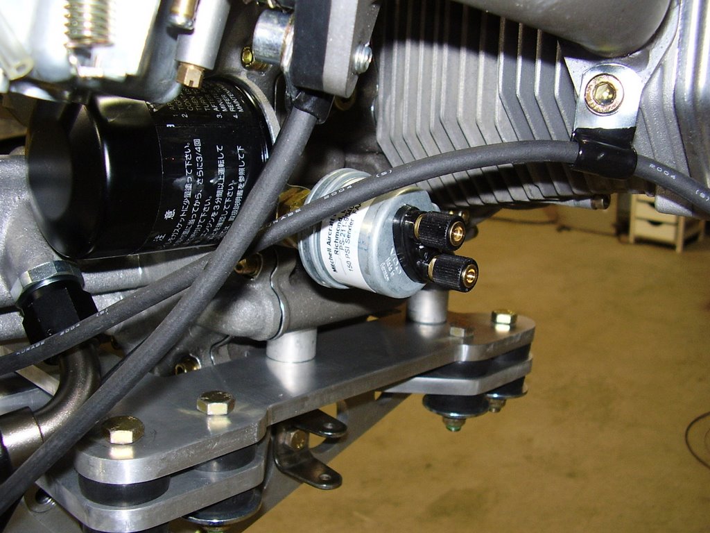
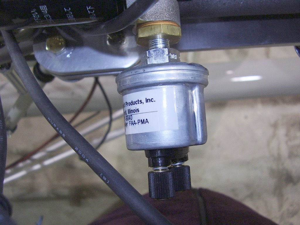
Today I bolted on an oil pressure sender to the engine. I purchased the sender from Aircraft Spruce. It is a 0-150 PSI unit from Mitchell


Saturday, April 01, 2006

Panel Wiring - 6 hour (214 Total)

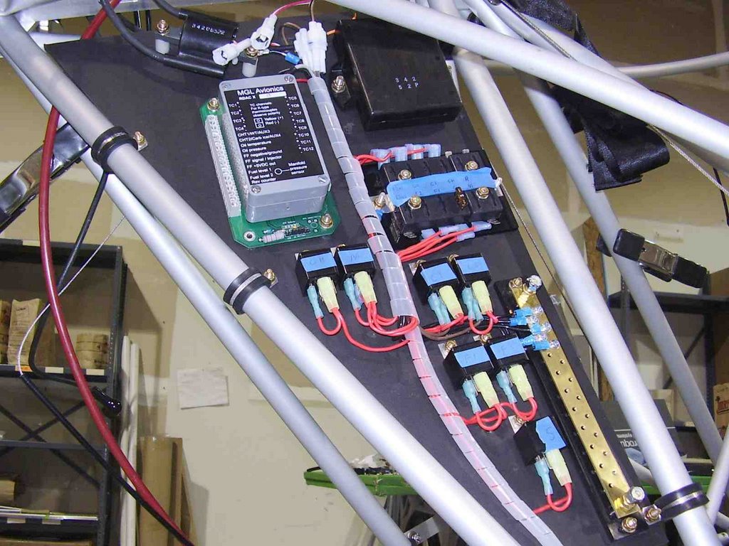
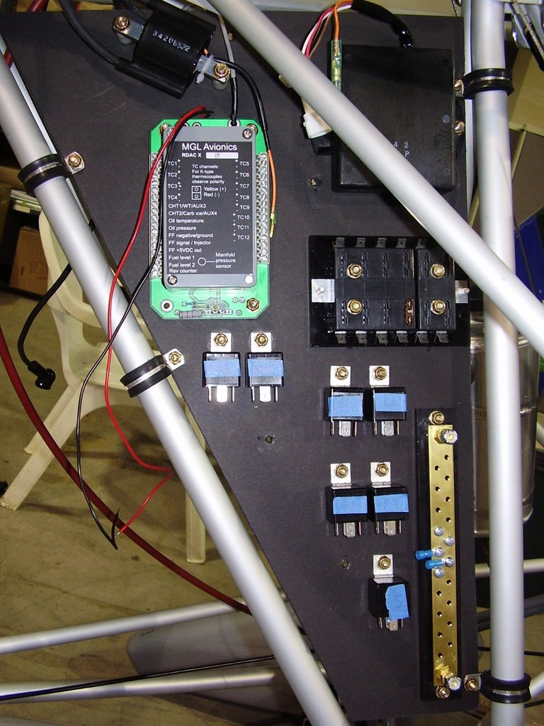
I spent several hours wiring the component of my electrical panel together. I am several hours from being finished but this is the majority of the power and ground wiring.

Thursday, March 30, 2006

Sparkplug Wires - 1 hour (208 Total)

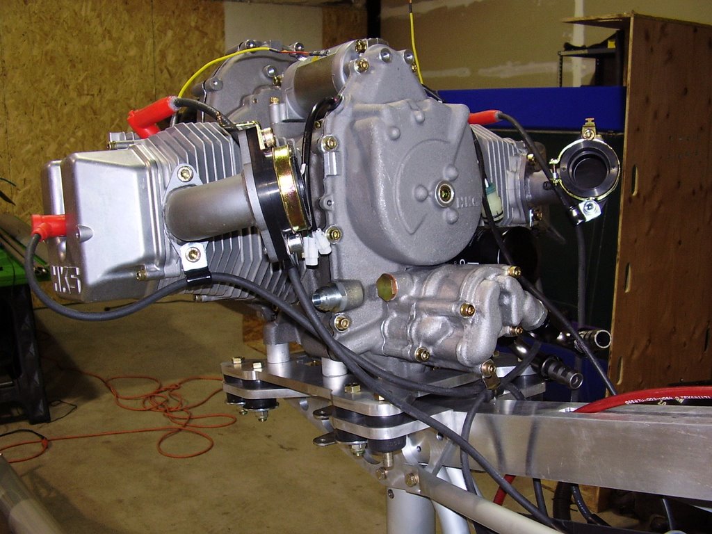
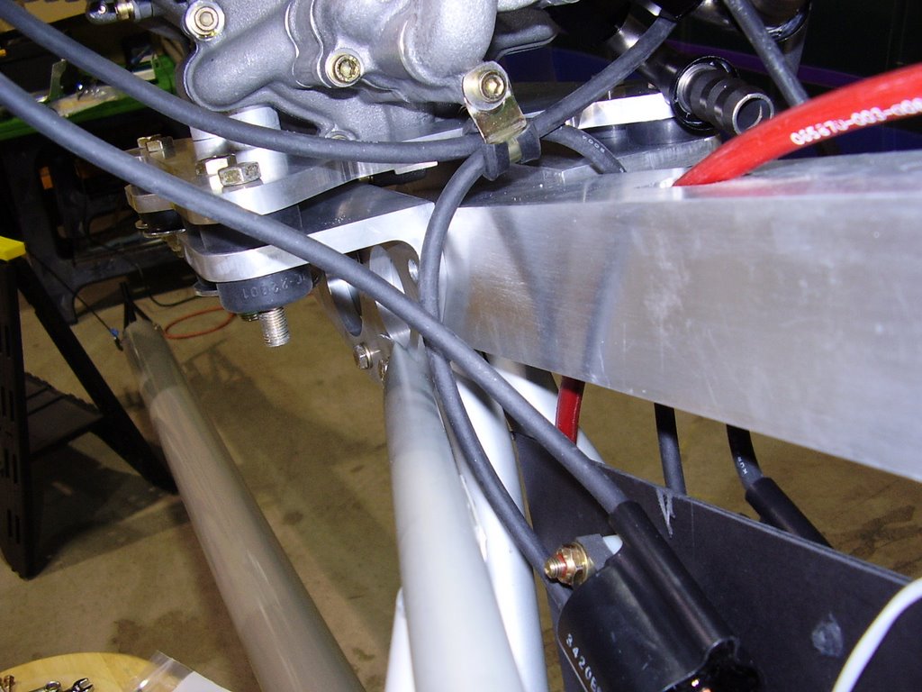
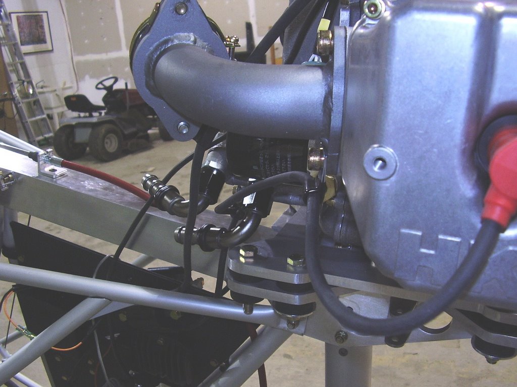
Today I routed the sparkplug wires. This required five different wire clamps to keep the wires from rubbing on any of the metal components.

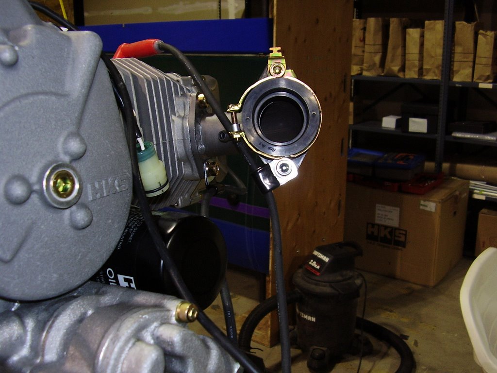
I needed to replace the lower carb bolts with a longer ones to accommodate the wire clamps.


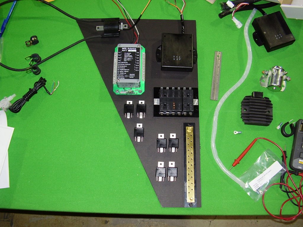
Electrical Panel - 4 hour (207 Total)

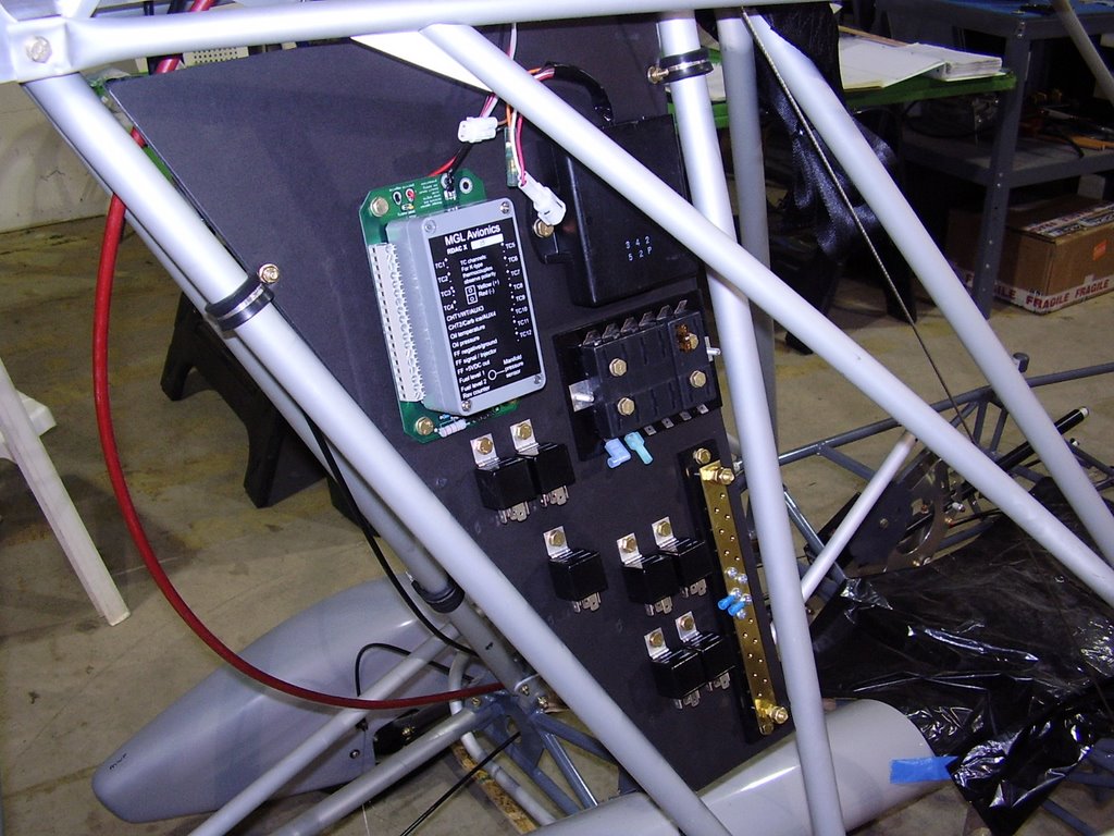
Over the course of several days, I laid out my electrical panel.

I started out by cutting out a piece of cardboard that fit the dimensions between the middle and rear cabanes. After laying out all of my electrical components on the cardboard and determining the best layout, I bolted the components to the cardboard.

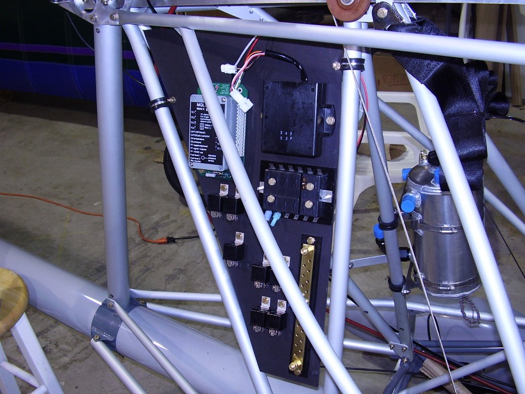
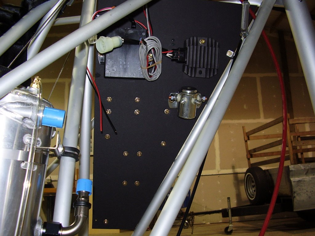
I originally thought that I would use two panels, one on the left and one on the right, but it turned out I could use one large panel if I used both sides.

I then installed my cardboard electrical panel into the plane. Once in the plane, I did some adjusting of the components to facilitate wiring.

I intend to completely wire the engine and panel to insure proper fit before replace the cardboard with a piece of sheet metal.


Saturday, March 25, 2006

CHT and Oil Temp Probes - 1 hour (203 Total)

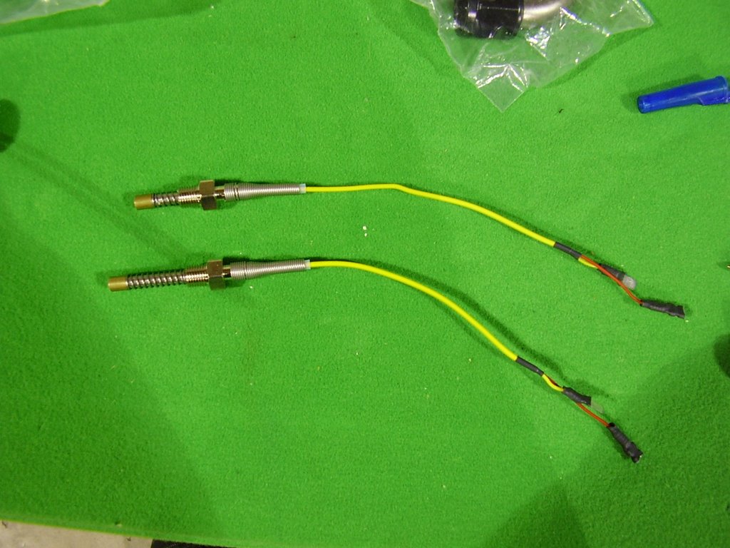
Today I installed my CHT and oil temp probes. These probes came with my Stratomaster instrument package from MGL Avionics.

To allow the CHT probe to be fully installed into the hole provided in the cylinder head, I needed to shorten the probe's spring. Surprisingly, the spring was easily cut with a pair of wire cutters.

Prior to installing the probe, I added a generous glob of thermal grease to the tip of the probe.

I used a pair of vise-grips and a socket to tighten the probe. I tightened to a snug fit.

The oil temp probe threaded directly into the opening provided in bottom of the oil tank. I used Teflon tape to seal the threads.


Monday, March 13, 2006

Oil Tank - 1 hour (202 Total)

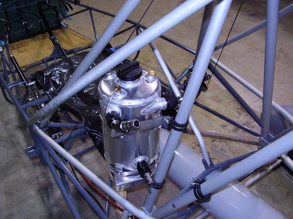
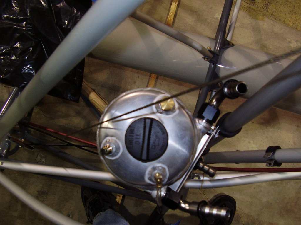
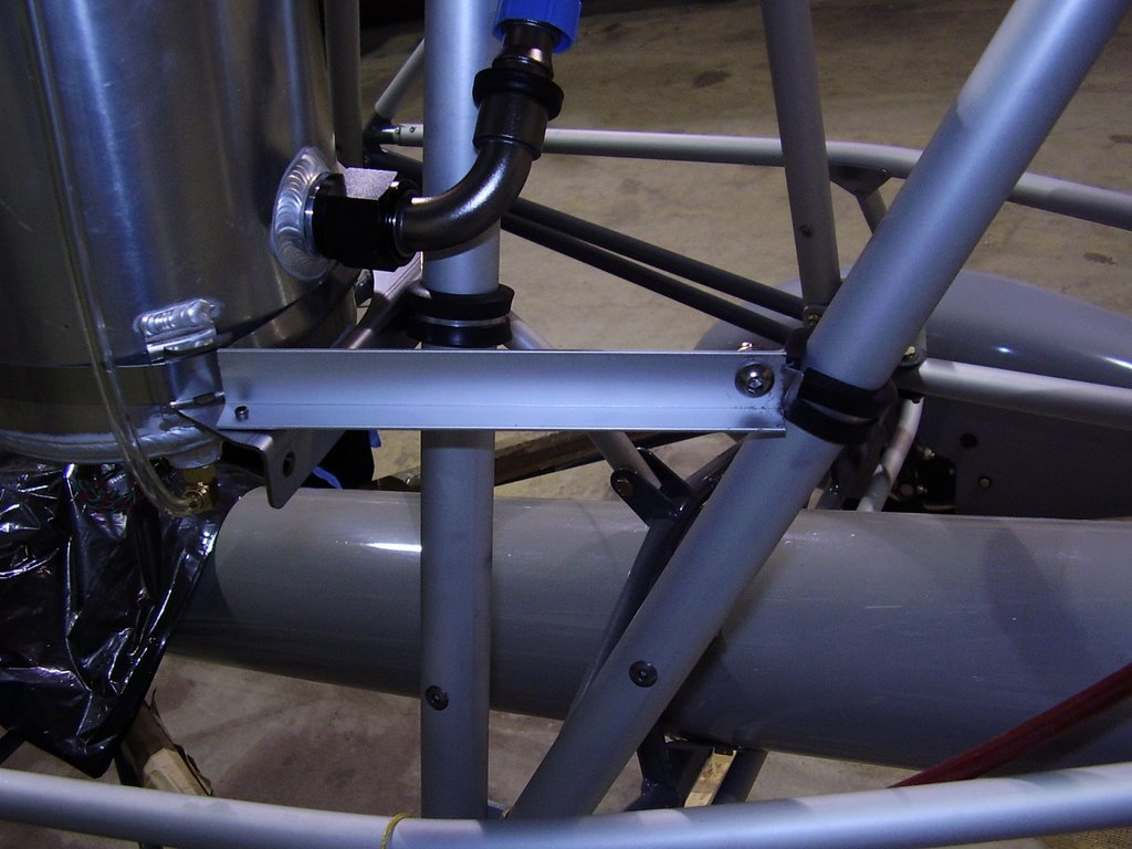
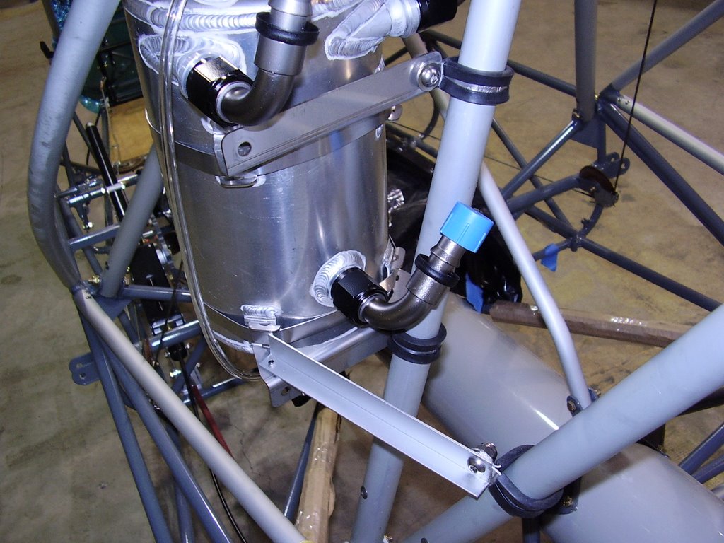
After many hours of holding the oil tank in different positions around the plane trying to find the optimum location, I finally decided to mount it on the middle cabane on the left side.

This location will give me easy access to the take from the door allowing easy filling. It will also allow easy draining since there is plenty of clearance between the drain plug and any obstacles. Since it is mounted between the left cabanes and left wall, it is making use of space that would normally be wasted. The tank needed to be oriented just right so it doesn't come in contact with the planes skin or the aileron cable.

A few negatives of this location are: The sight tube will be difficult to see but I may be able to see it from outside the plane through the left window. This location is also close to my head. If there is considerable noise from the sloshing of the oil, I may have trouble with keeping my bladder comfortable!

I mounted the oil tank using 1" cushioned wire clamps. Placing two clamps on the middle cabane but in opposite facing directions allowed me to compensate for the left-right angle the cabane sits at. I used a piece of aluminum angle mounted from the tank bracket to the rear cabane to keep the tank from rotating around the middle cabane.

I needed to attach the tank's mounting bracket in a funny fashion to get the fittings to face the rear of the plane.


Saturday, March 11, 2006

Mounting Engine - 2 hour (201 Total)

With the help of a few friends, I removed the wings from the plane. This was necessary to install the new engine brackets.

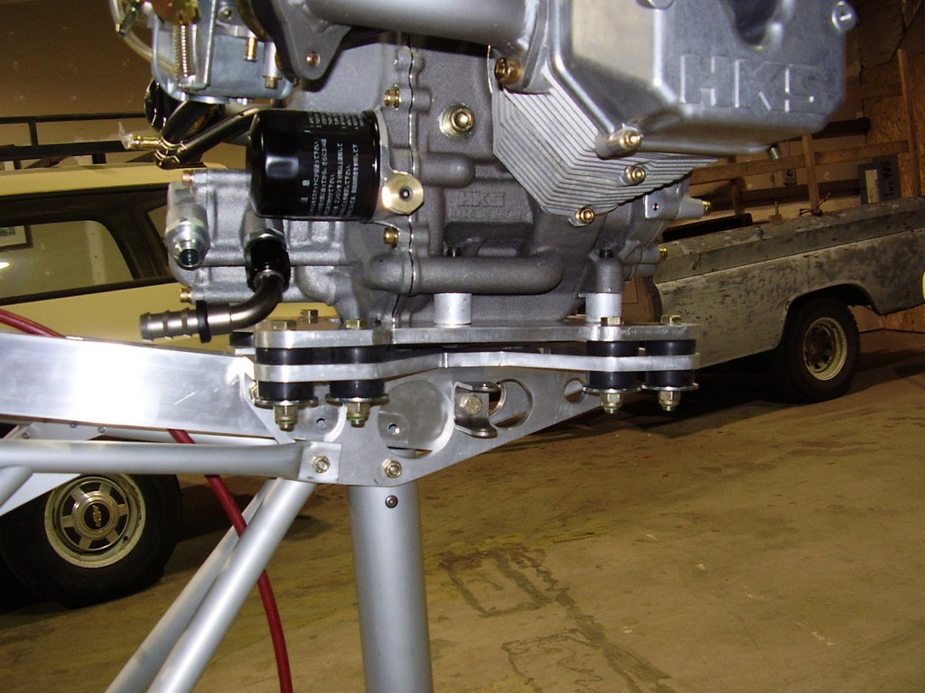
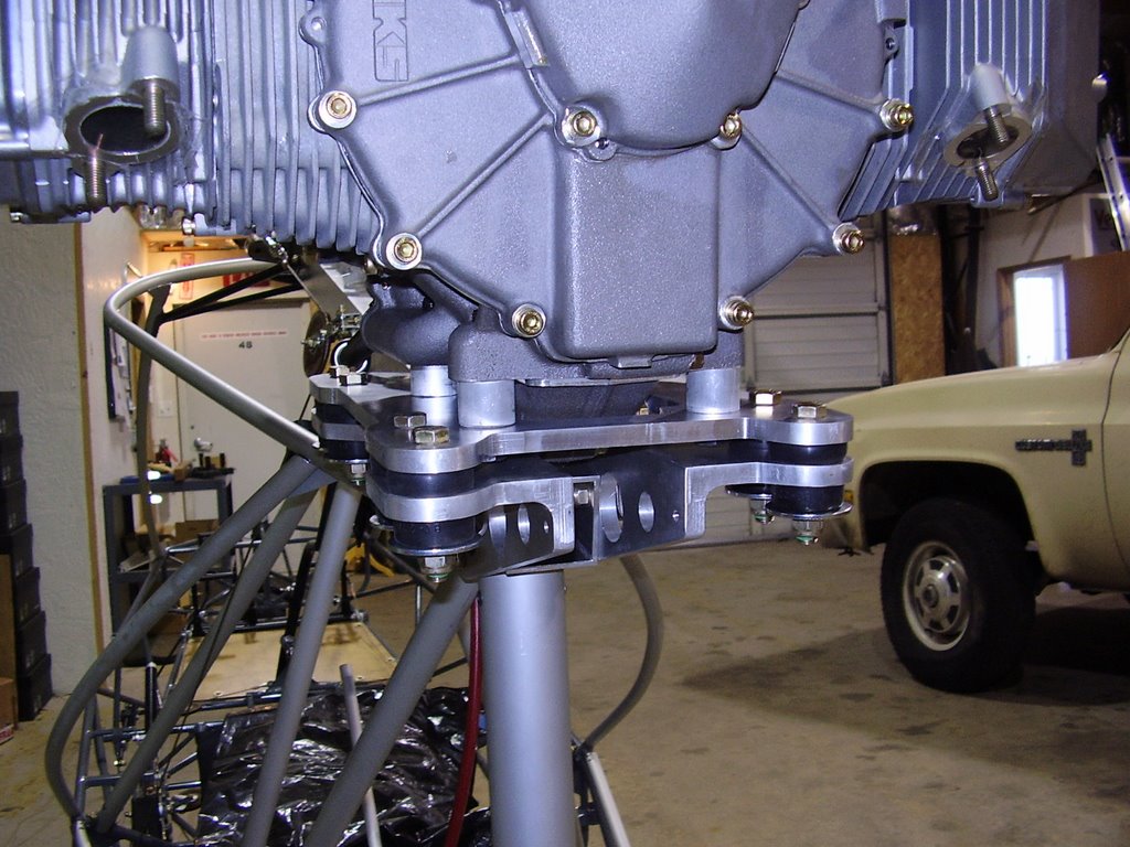
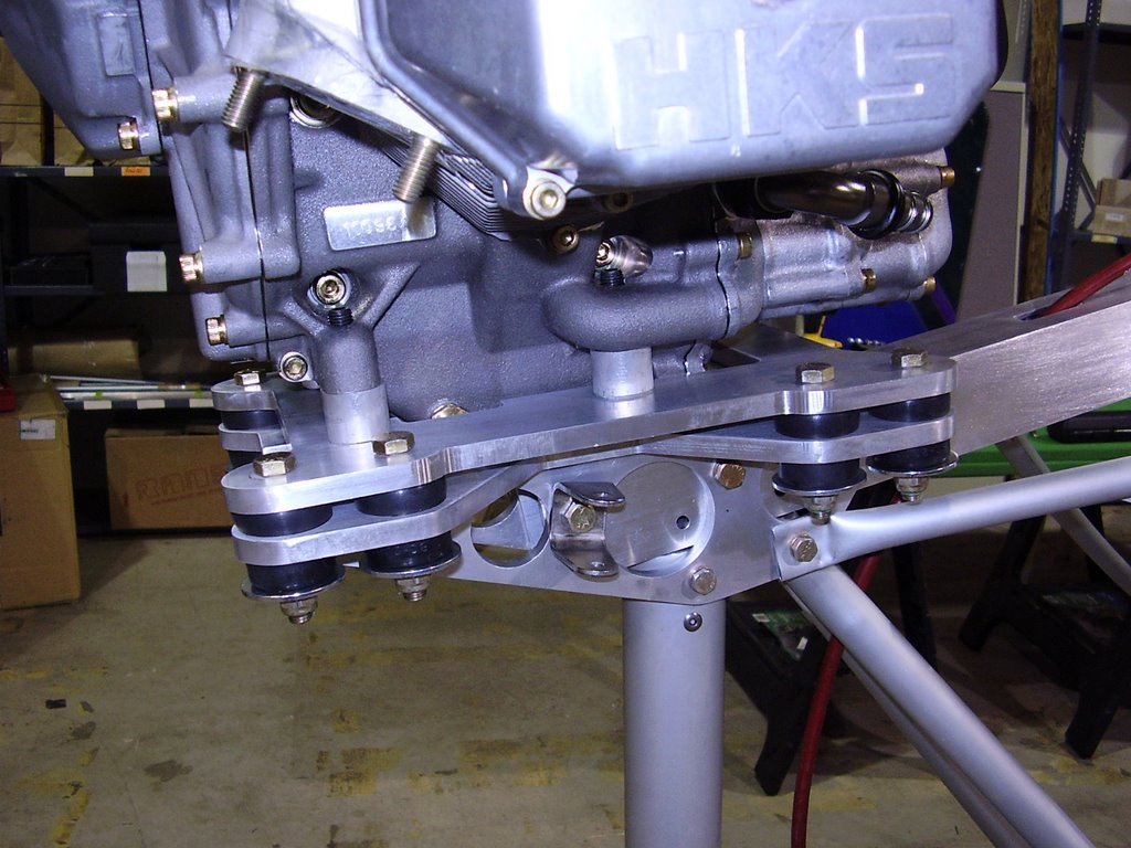
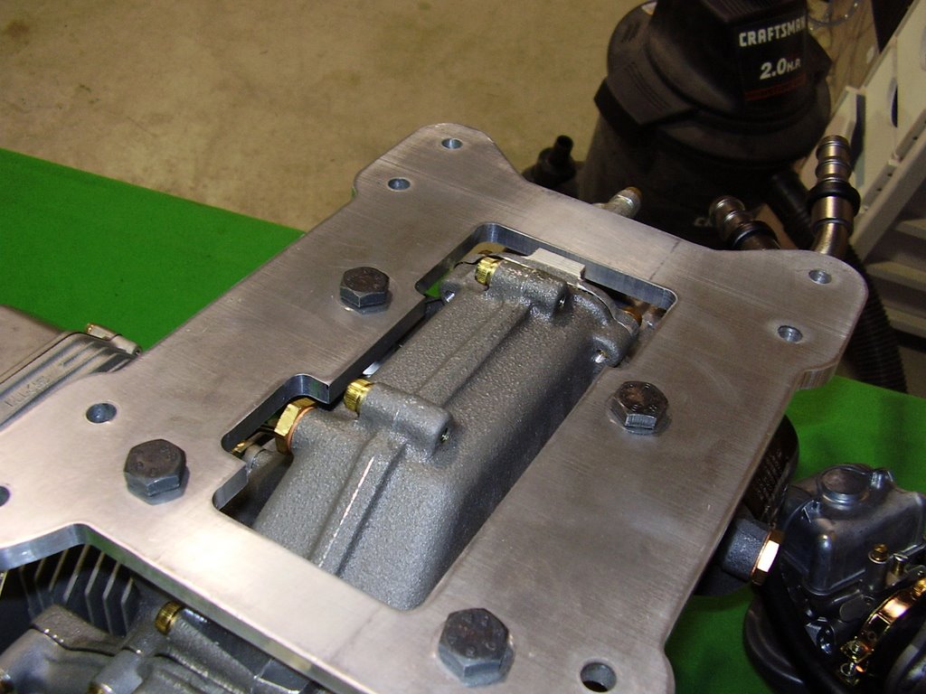
I then installed the new engine bracket and mounted the engine. I tightened the four bolts that hold the engine to the plate to the proper torque specified in the HKS manual. Since the tips of the bolts protrude through the engine block, I intend to mark the bolt with nail polish so I can quickly check the bolts during my pre-flight check.

I also tightened down all eight Barry mounts until they were snug. I used soft Barry mounts.

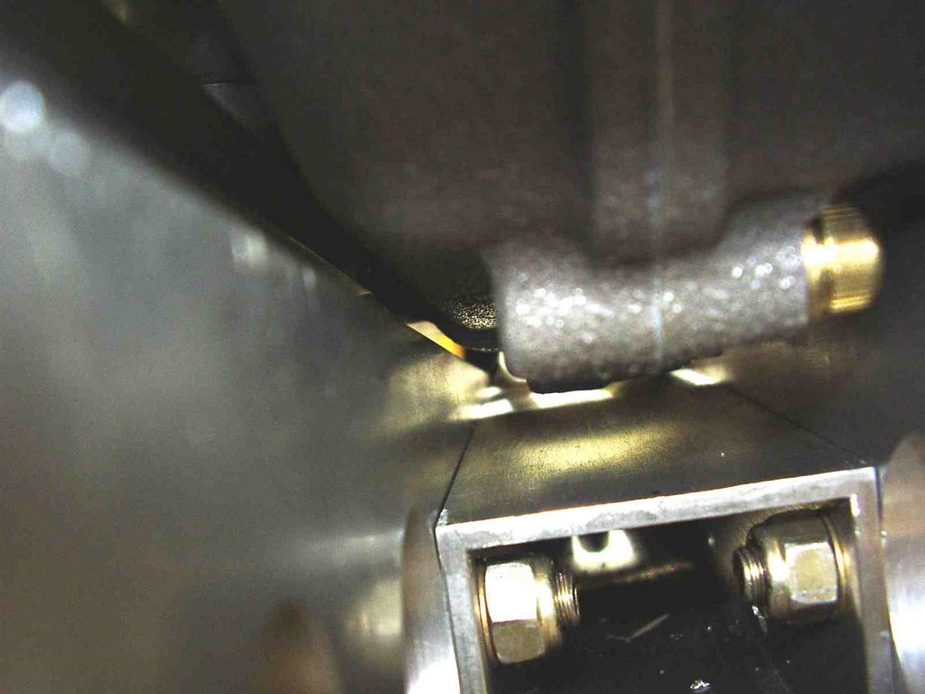
The new mount has resolved most of the clearance issues that the original had. The spacing between the sharp corner of the mount brackets and the bottom side of the engine is still close at 3/32". If the spacing proves to be too little, a simple solution would be to round over or chamfer the sharp edge of the bracket to increase the clearance.

The oil fitting clearance was also resolved but the type of fittings that can be used is limited due to the spacing. The 90 degree fitting I'm planning to use just barely clears the bolt head.


New Engine Mount - 0 hour (199 Total)

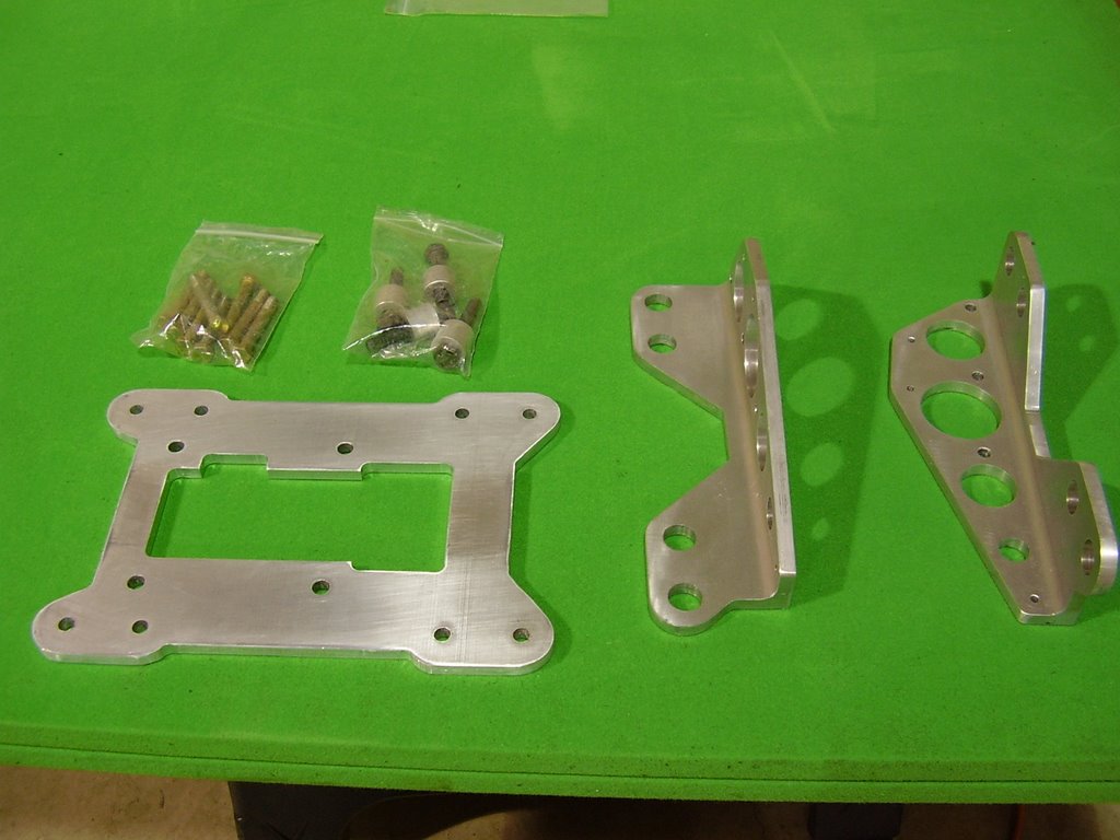
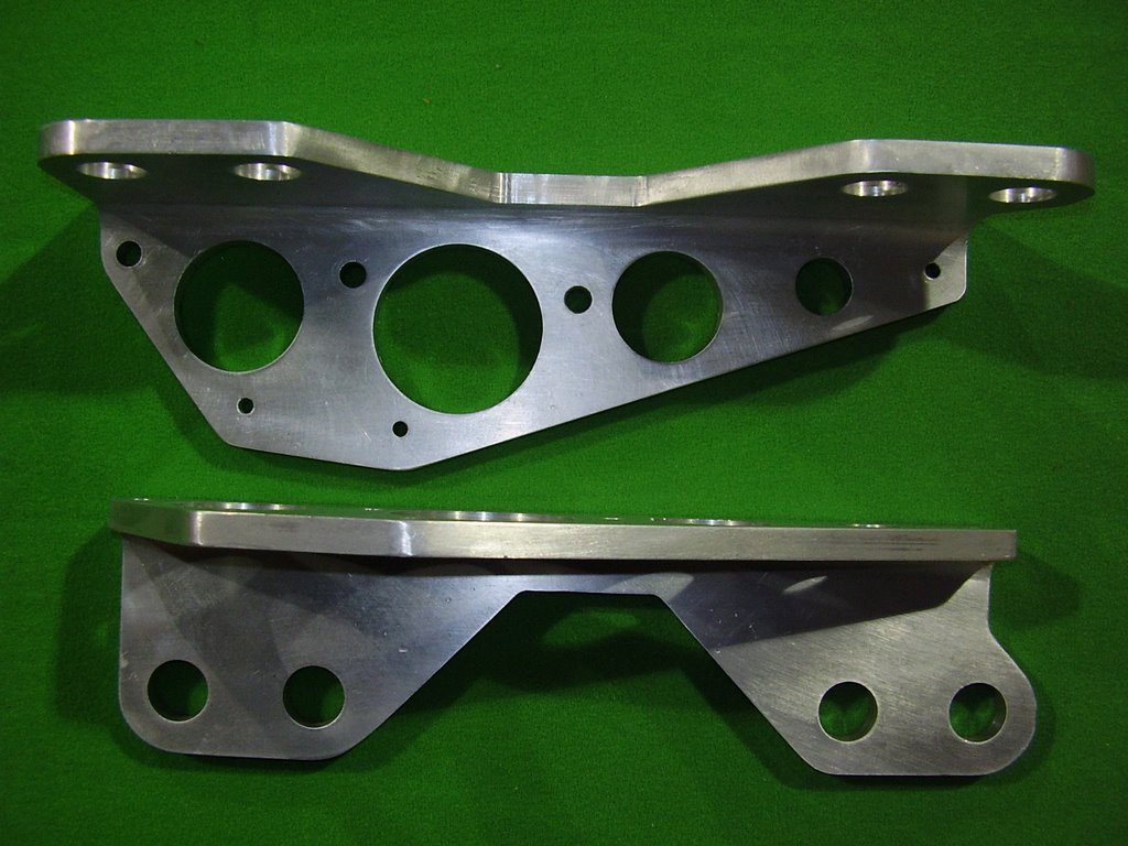
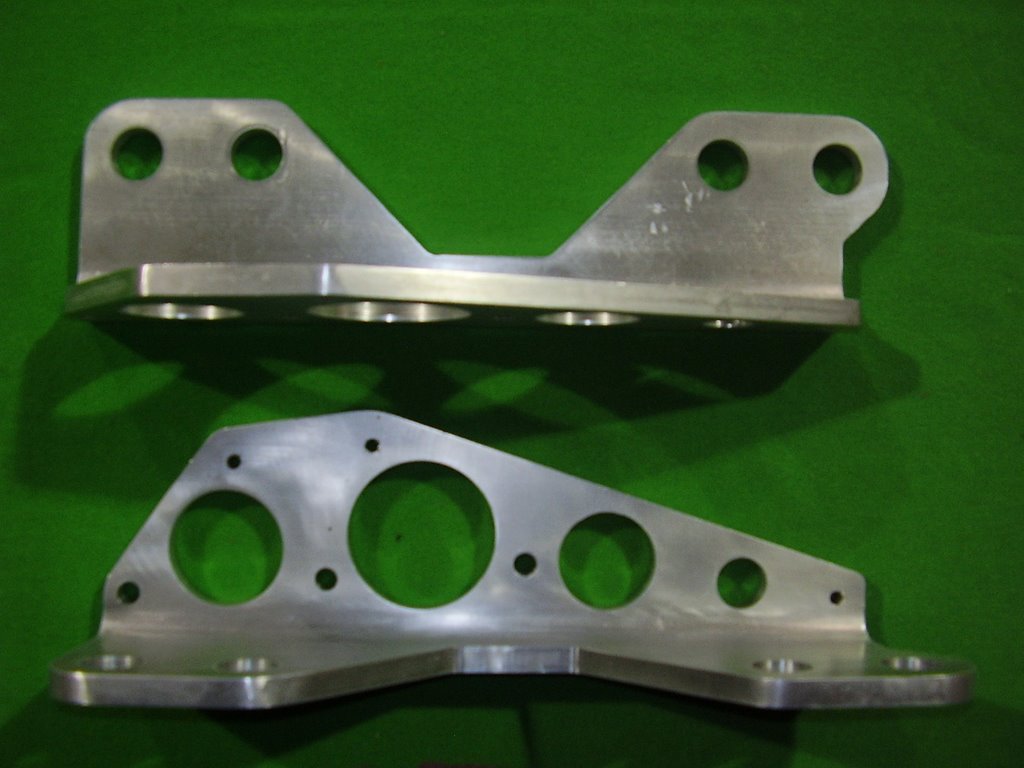
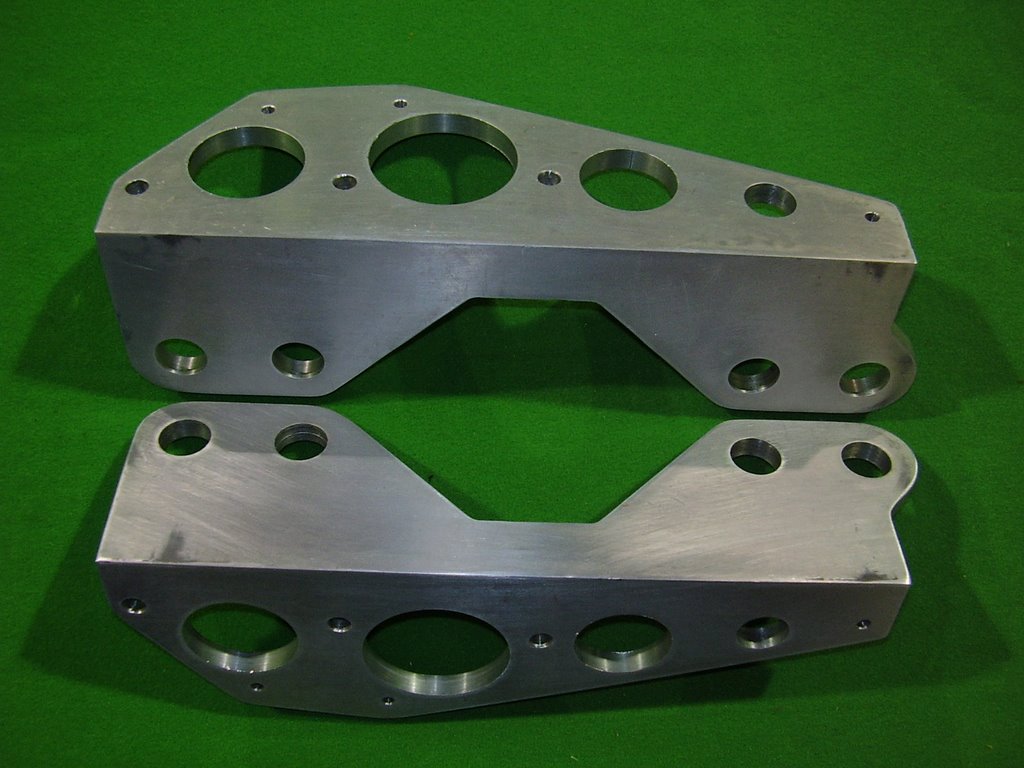
I received my new engine mount from Green Sky Adventures. Jerry did some clean up of the mount prior to sending it to me so it is much prettier than the first. Jerry also did a test fit of the mount on an engine.

Overall the mount looks good but the two smaller holes in the bracket needed to be drilled out to accommodate the 1/4" bolts. This was an error that I didn't catch in the design files.


Friday, March 10, 2006

Lift Strut Fairings - 1 hour (199 Total)

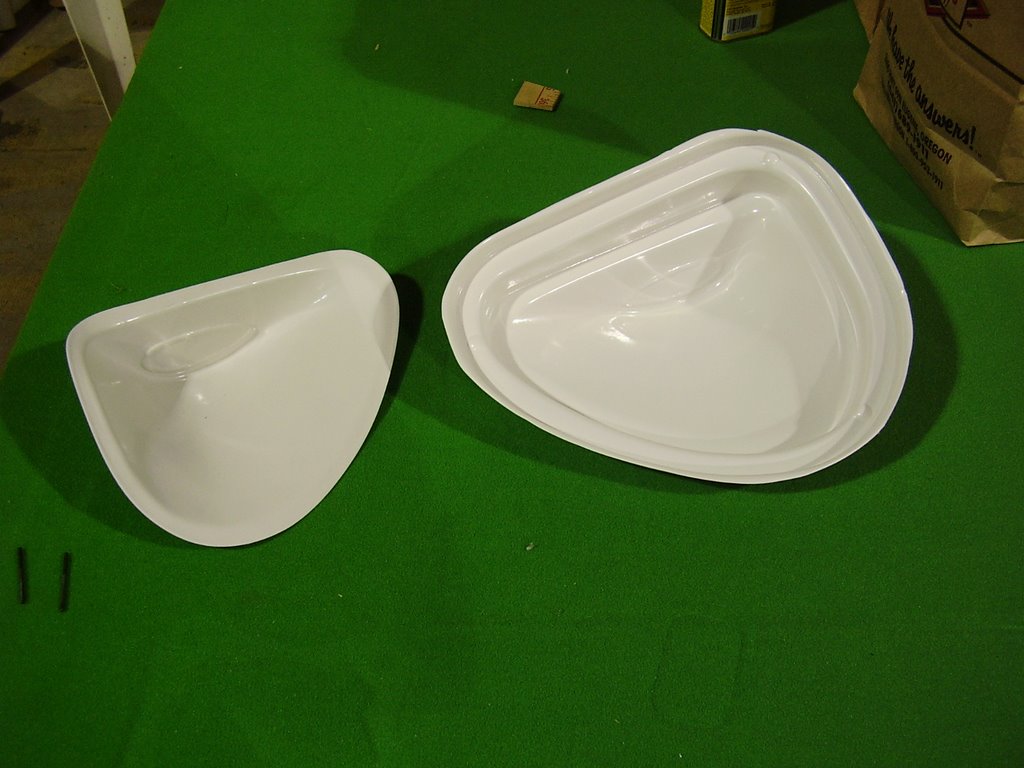
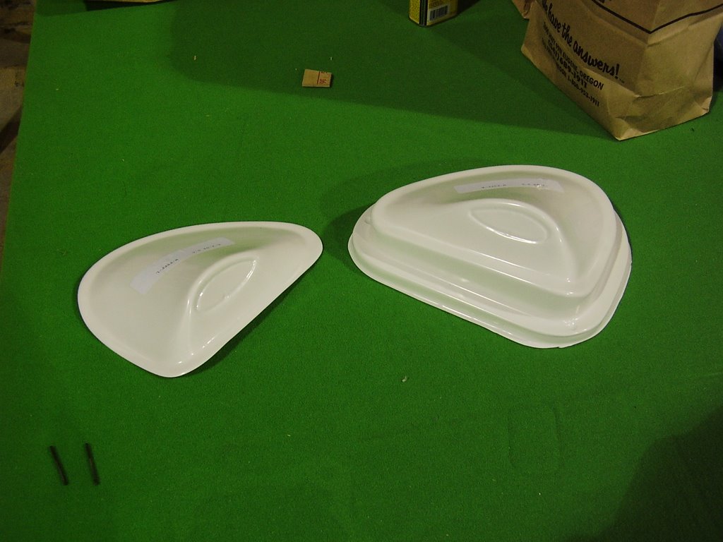
Today I started working on the Lift Strut Fairings. I didn't get very far before I decided that I didn't want to use them.

The Rans literature shows them as being made out of Lexan; these are made of some type of opaque plastic that wont allow me to see the bolts inside during pre-flight inspections.

After I cleaned up the first fairing, I put it on the wing to test it's fit. The most noticeable problem was the forward lip did not have enough curve to it to fit against the Leading Edge Spar. I could have trimmed this off to allow a better fit but the directions called to have a foam rubber seal added to prevent air flow between the fairing and the wing. Trimming the fairing would remove the lip that the seal is suppose to stick to.

I also didn't like their suggested attachment method of using screws without any type of vibration proof locking method.