Thursday, March 09, 2006

Jury Struts and Fairings - 12 hours (198 Total)

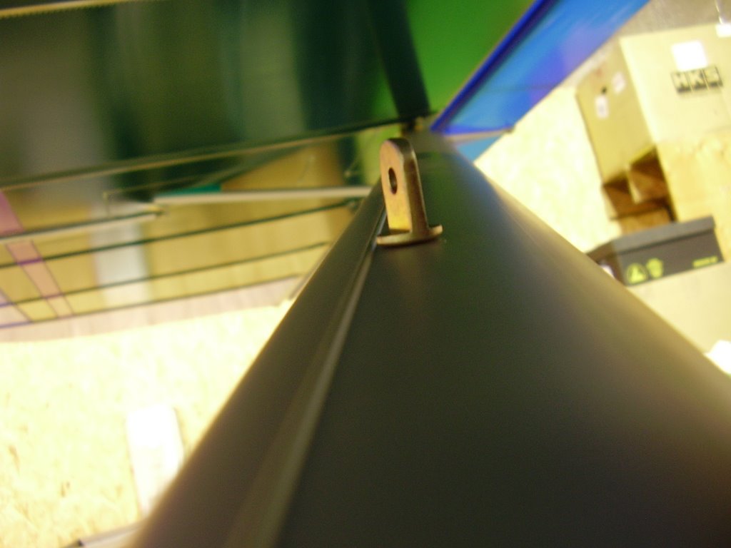
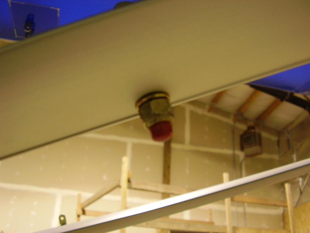
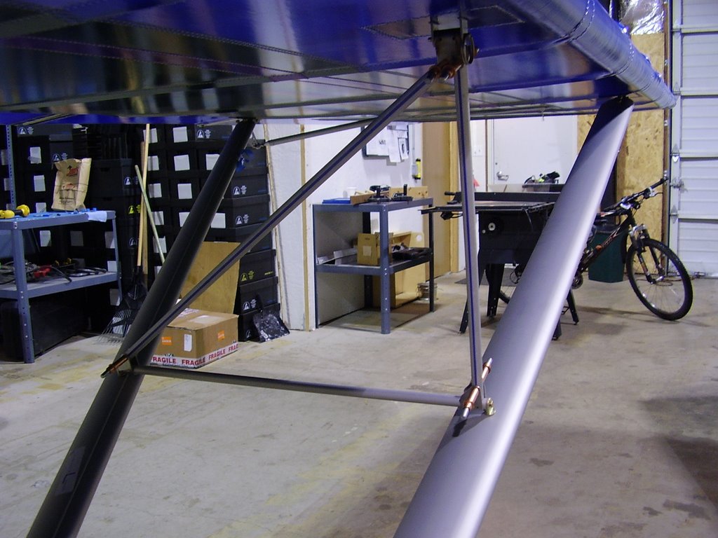
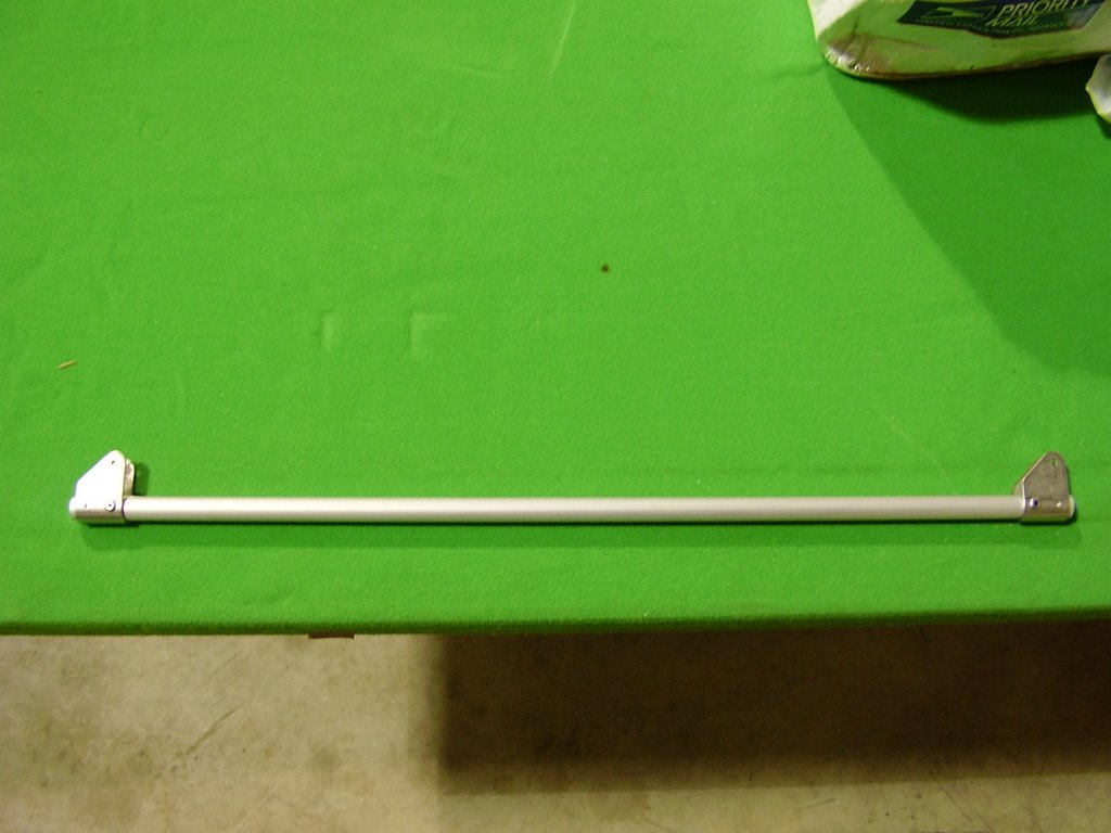
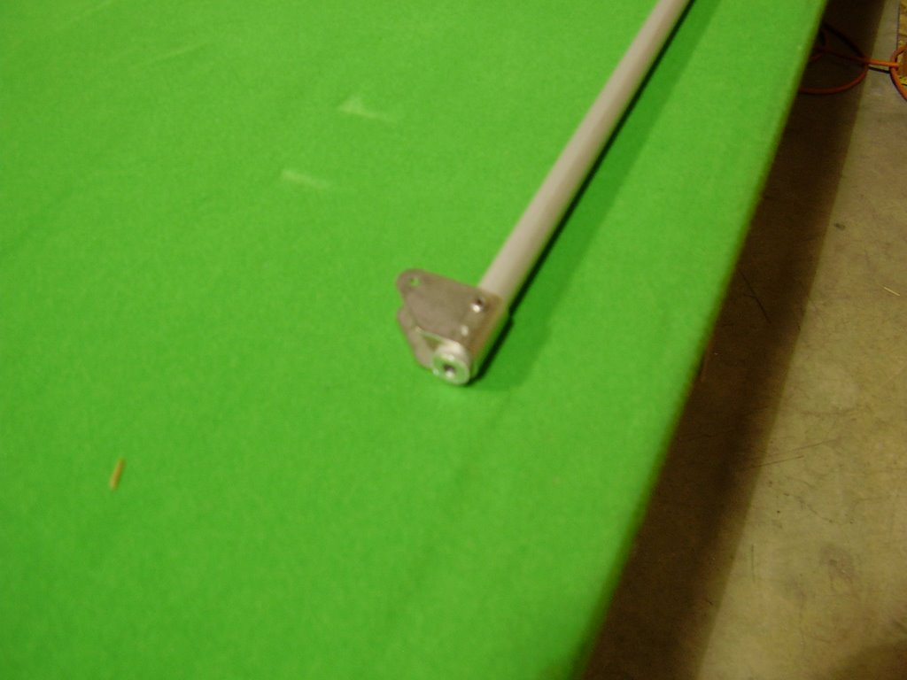
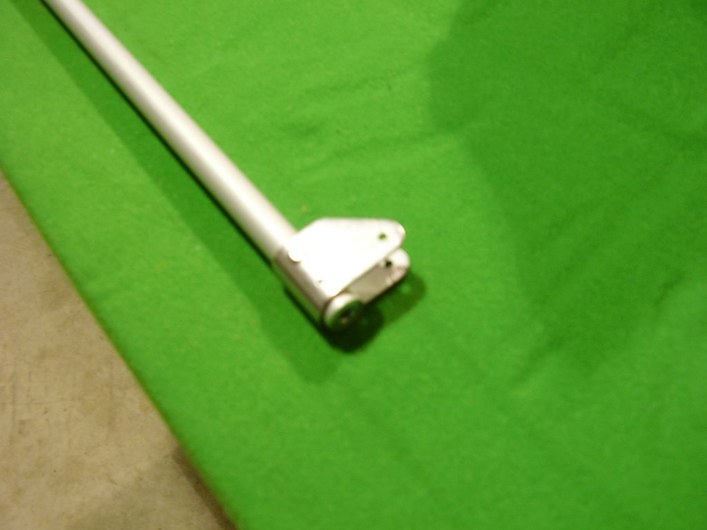
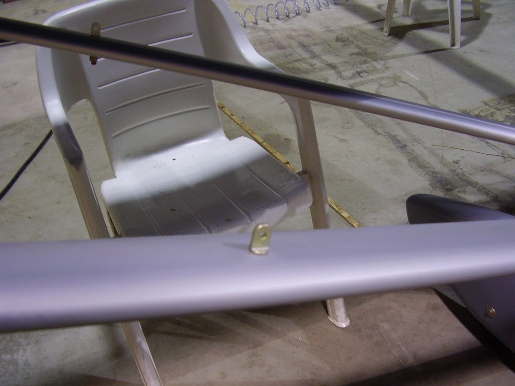
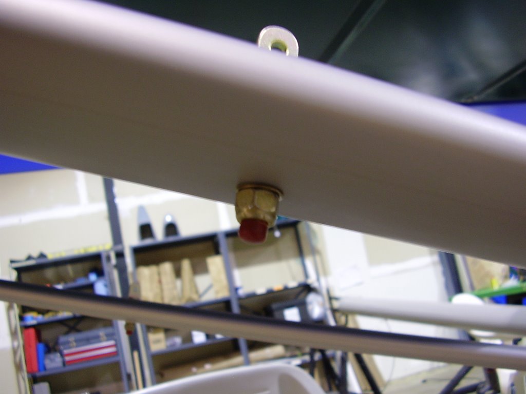
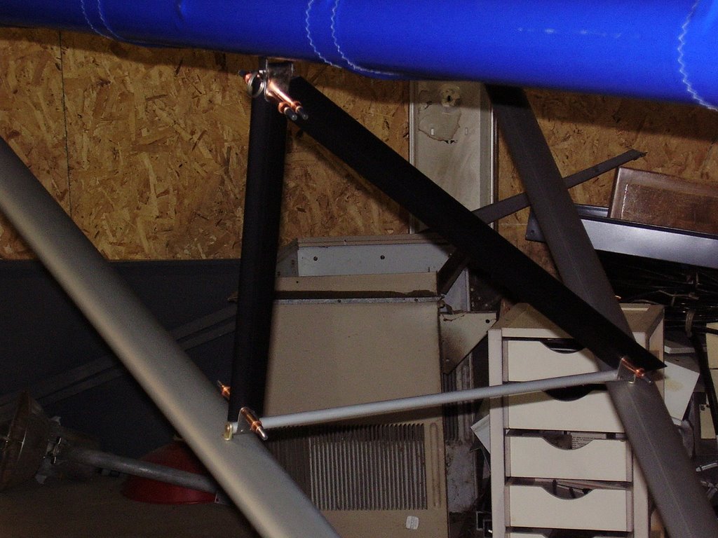
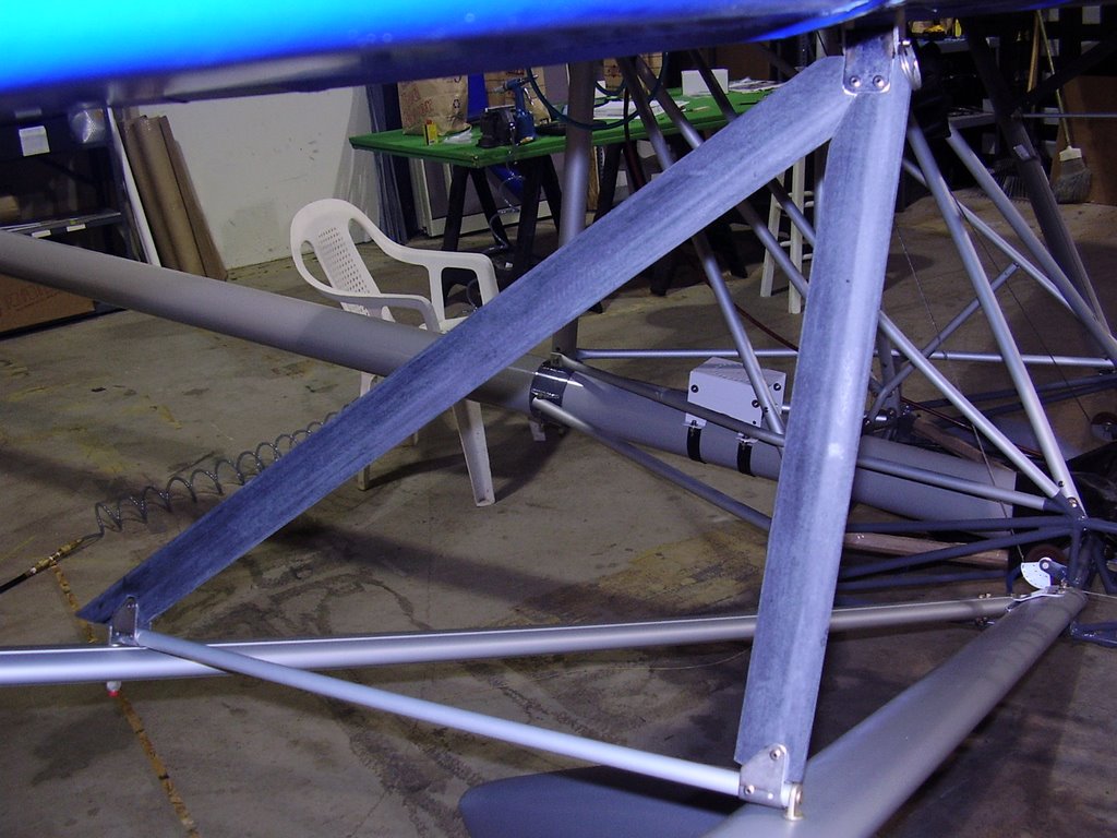
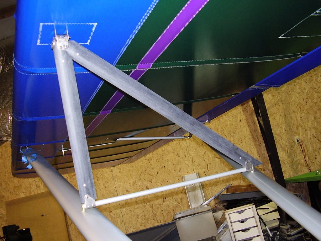
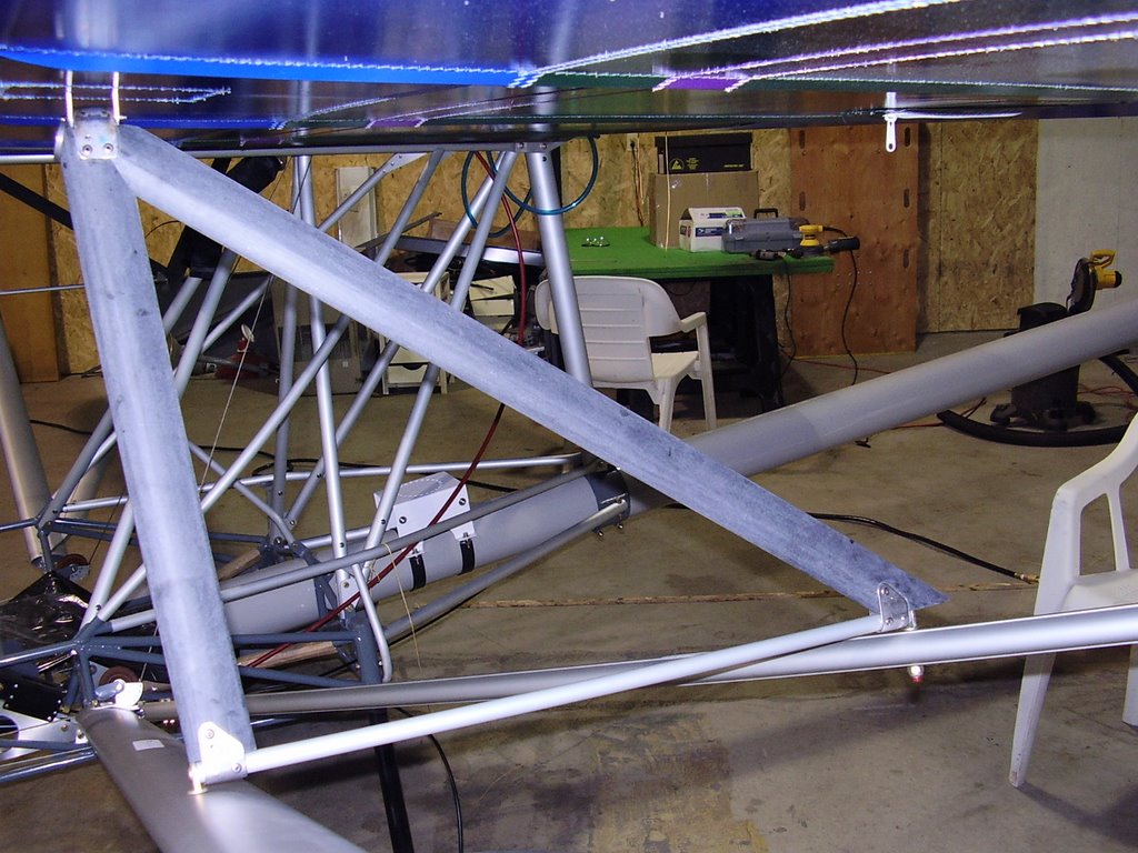
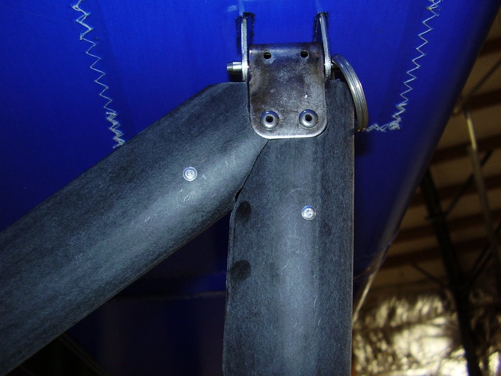
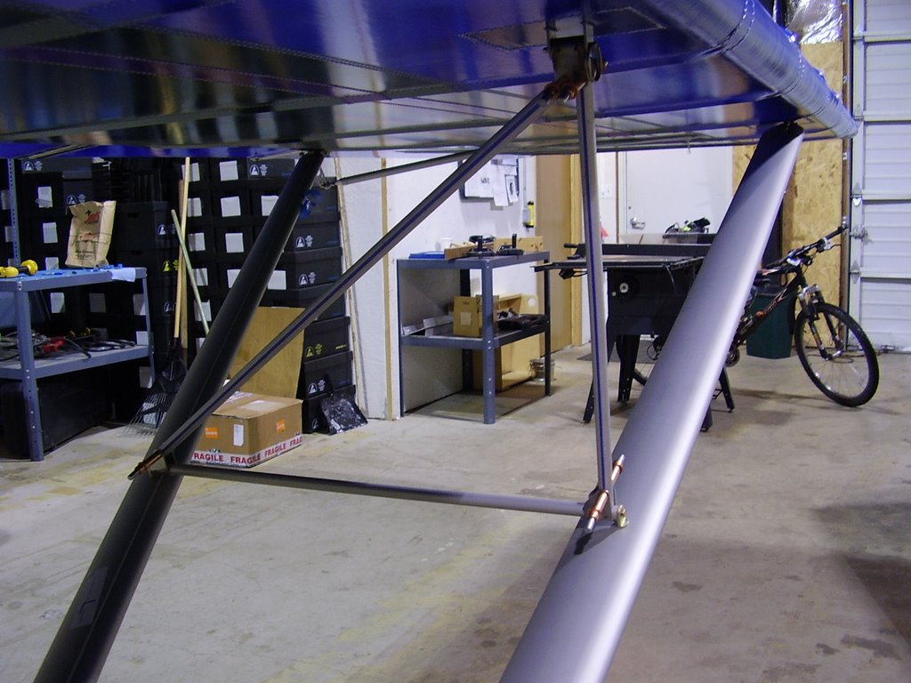
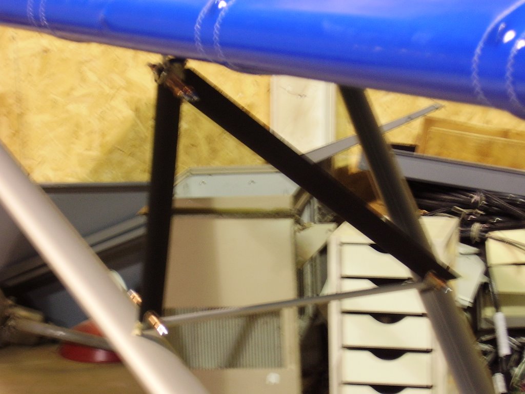
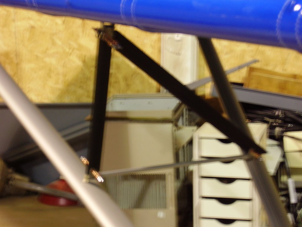
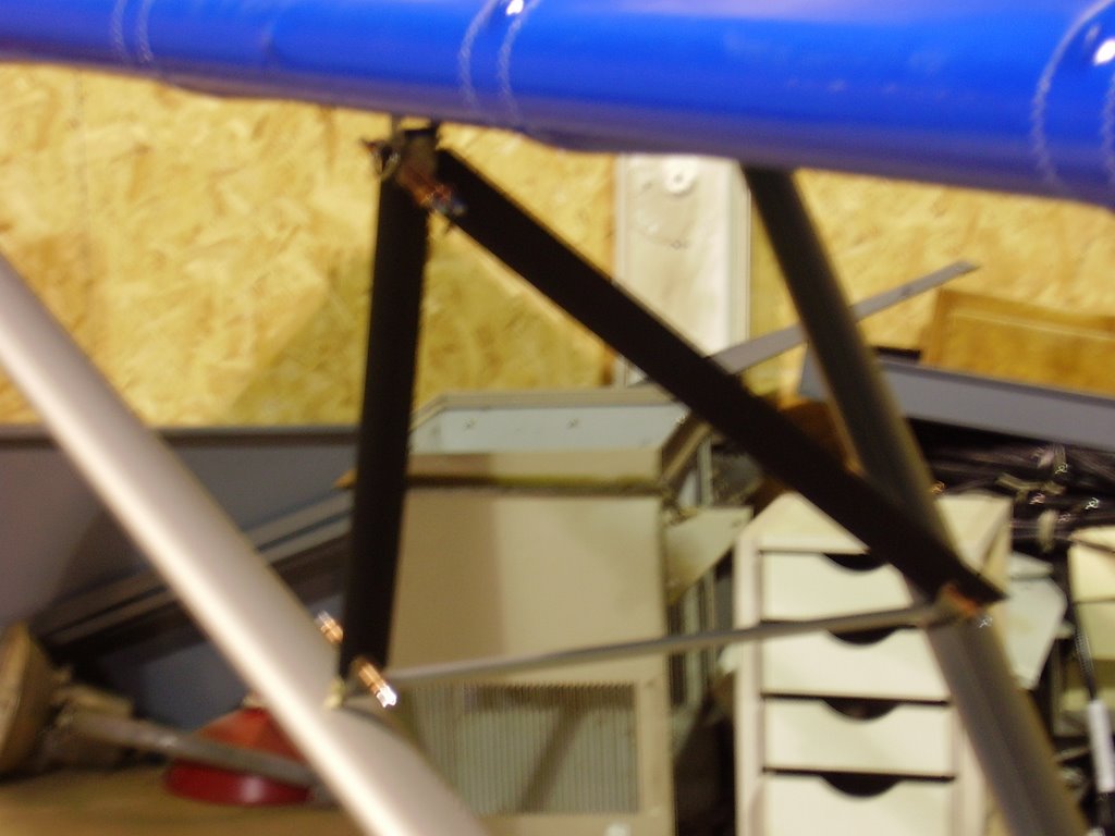
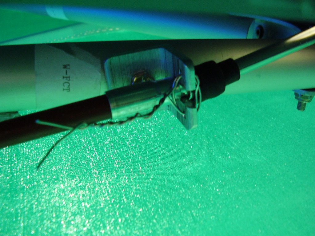
Over the course of three days, I assembled my Jury Struts and Jury Strut Fairings. This was a tedious and time consuming process. The main reason for this was the fairings needed to added prior to riveting the Jury Struts completely together.

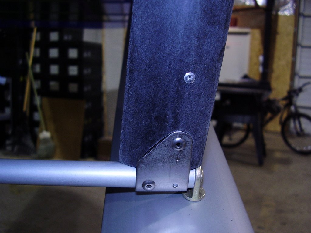
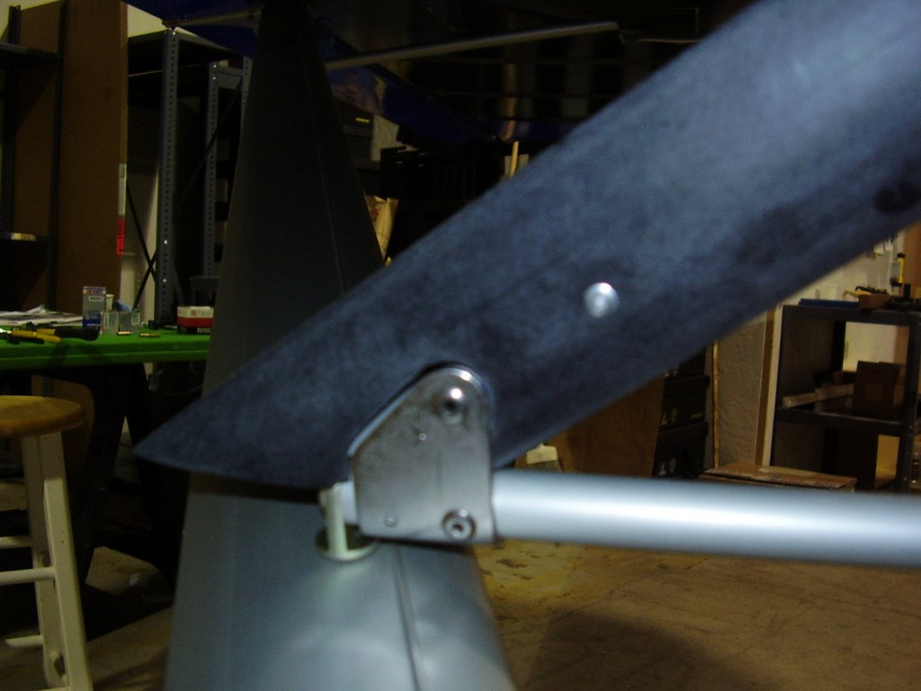
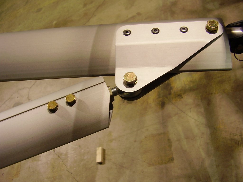
I started out by drilling the holes in the Lift Struts for the eyebolts. Once the eyebolts were installed I cut the bottom portion of the Jury Strut to match the distance between the eyebolts on the Forward Lift Strut and Rear Lift Strut. I cut the aluminum tubing slightly long so it would be slightly compressed when installed. The lengths varied by ~1/16" between the left wing's Jury Strut and the Right wing's.

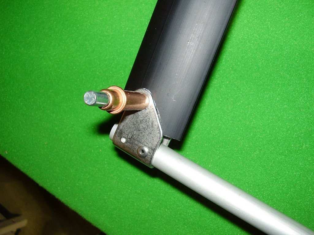
I then inserted the drilled out aluminum bushings into the rod ends. To give them a snug fit, I only inserted them part way before using the punch to dimple the tubing. I them pressed the bushings all the way in.

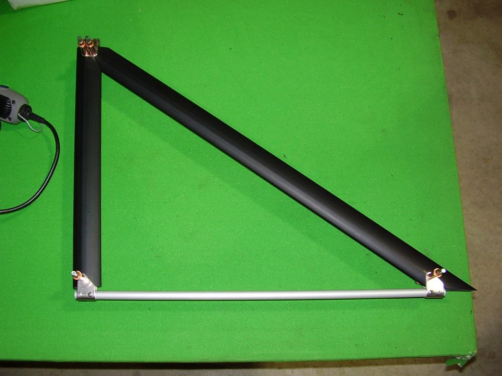
I then drilled and riveted the stainless steel hardware to the bottom Jury Strut pieces. I placed the parts on a hard flat surface to insure that the pieces were lined up during this process.

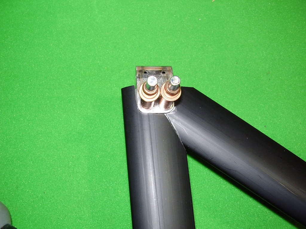
Once the bottom pieces were complete I cut and assembled the other two sides of the Jury strut. I relied on measurements instead of the lengths suggested in the manual. I used a pen to mark a straight line down the length of the tubing to use as a reference to insure the pieces were drilled and assembled without any twists. At this point I used Clecos to assemble to pieces together. Rans only provided 12 clecos with the kit so I was only able to have one assembled at a time.

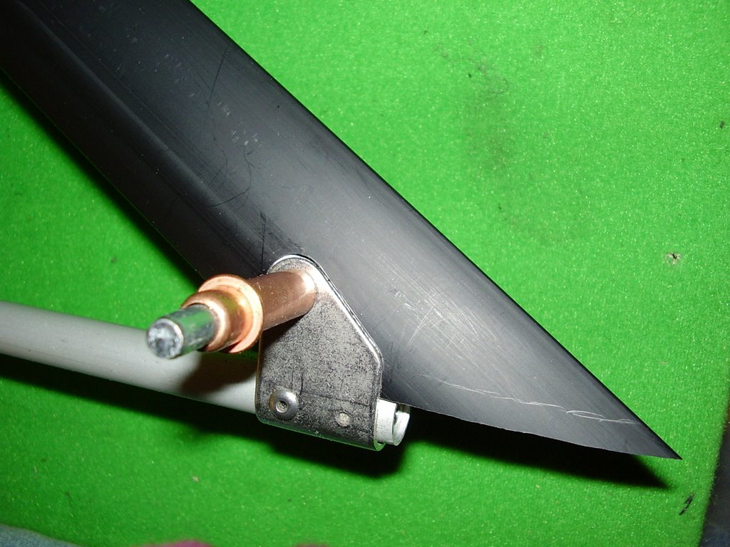
Once I had the Jury Struts assembled (with clecos) and verified they fit onto to wing, I started working on the fairings. I used my Dremel tool to carve away at the plastic fairing material to insure a tight fit. This was a time consuming process since I needed to assemble and disassemble the Jury Strut each time I would test fit the fairing.

Since I wanted to wait until the very end before I drilled the extra holes in the stainless steel hardware that Rans called out to reinforce some of the connections, the top hardware had the tendency to twist or rotate. This hardware connects to the wing with a clevis pin so it's alignment is crucial. To insure proper alignment, I marked both the tubing and hardware while they were installed onto the wing. That way when I was working on the fairings, I could rotate the hardware back to the correct position if it was inadvertently twisted.

Once I was happy with the Jury struts and fairings, I took them apart, cleaned up the edges and marking and sanded the plastic fairing material so it would accept the paint easier. I then riveted the pieces together and performed one last trial fit. I then drilled holes in the stainless steel hardware and tubing for the extra rivets. I also installed the aluminum rivets into the fairings to prevent them from twisting.

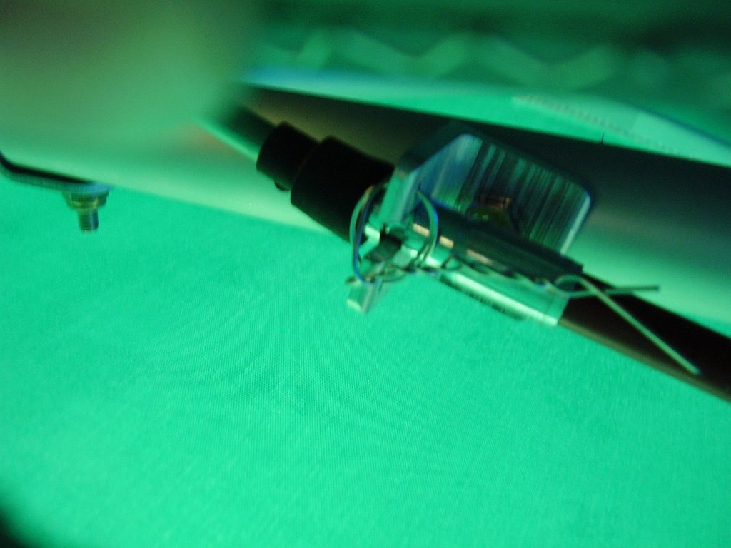
I did not drill out the hole in the Drilled Aluminum Bushings for the cotter pin. I have heard that this attachment method is prone to failure due the the wing vibration wearing through the cotter pin. I will look to see if I can find another attachment method that can handle the vibration better.






Saturday, March 04, 2006

Setting Washout - 1 hour (186 Total)

With the help of a couple of friends, I set the washout of my wings. Rans design calls for 1/4" of washout measured between the root of the wing and where the lift struts meet the wing. This raising of the trailing edge spar gives the wing tip a slightly reduced amount of angle of attack. This makes the plane more stable by causing the wing tip to stall at a lower speed than the root of the wing so when a stall occurs the plane will be less likely to "drop a wing."

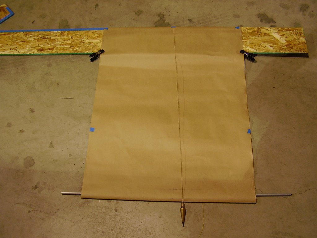
Since my wing fabric is already installed, I needed to find another method to set the washout other than the method Rans describes in their manual. My approach was to attach a large piece of paper to a straight edge and hold it against the bottom of the wing near the root. I drew a horizontal line on the paper 43.5" from where the straight edge meets the wing. This is the same distance as the center to center spacing of the Leading Edge Spar and Trailing Edge Spar. I then used a plump-bob to mark off where the string intercepted the long horizontal line. This is my base line mark.

I then moved the jig to the location the lift struts meet the wing and made a second mark. The goal is have the second mark be 1/4" forward of the base line mark. I adjusted my adjustable lift strut until I achieved this.

Because of the fuel tank and the fuselage got in the way of my straight edge, I wasn't able to make my baseline mark directly at the root. I took my base line mark ~33" from the root. Since the lift struts meet the wing at ~108", my washout measurement should be 70% of 1/4" or 0.175".

I ended up setting the washout to pretty close to 1/4" because one half turn (minimal adjustment) of the eyebolt in the adjustable lift strut mechanism caused a 1/8" change in the washout! I decided it was better to have a little more washout than too little. Since it's adjustable I can always make changes later!


Saturday, February 25, 2006

Rigging Flaps - 4 hours (185 Total)

Today I finish rigging the flaps. I attempted to do this several weeks ago but was having difficulty because either the flaps would be too high or too low. Rans's suggestion for alleviating this issue was to trim the excess thread off of the teleflex cable. I trimmed 5/16" off of both teleflex cables above the cockpit. This allowed for only a couple of threads to remain before the teleflex bottoms out onto the bolt in the Insert Nut.

Rans also told me to set the teleflex retainer bracket so the angle was towards the front. Trimming the excess teleflex thread and having the bracket in this orientation only made the problem worse. By rotating the teleflex retainer bracket around, the problem was reduced but not solved.

I then trimmed off 3/16" of the left teleflex cable at the flap end. This turned out to be unnecessary because the Flap Lever Teleflex Cable was still adjusted. Luckily I didn't trim off too much. I did not trim the right cable.

I readjusted the Flap Lever Teleflex Cable so it was fully bottomed out. I then built a jig to allow me to accurately set the flap and aileron droop out of some plywood (actually OSB). This jig will hook onto the front spar of the wing and allow me to check droop of the flaps.


Once the flaps were adjusted, I safety wired the teleflex retainer brackets within the wings and placed the "safety brackets" above the cockpit.


I then trimmed the wing fabric around the flap teleflex cables to prevent rubbing. These did not come out as clean as I had hoped.


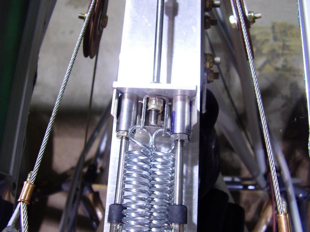
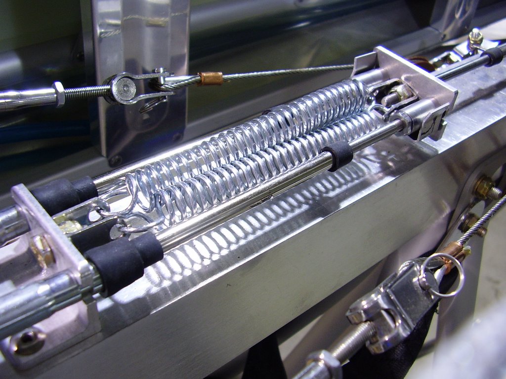
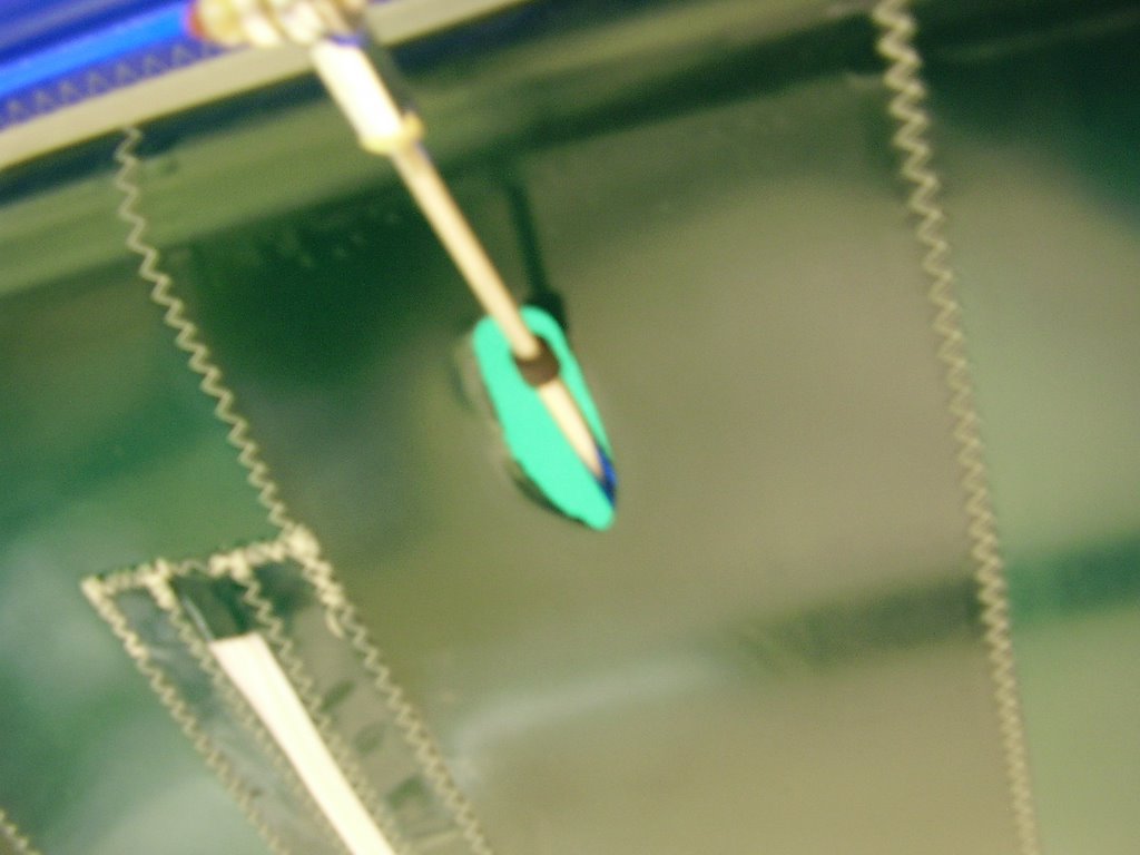
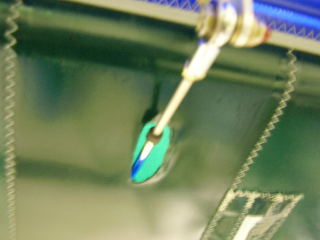
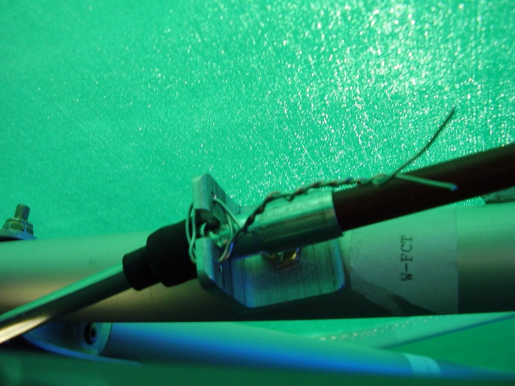
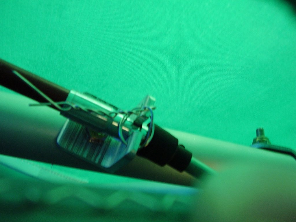
Here are pictures of the safety wire used on the teleflex retainer brackets within the wings.


Sunday, February 19, 2006

Nose Cone - 3 hours (181 Total)

Today I assembled the two halves of the nose cone. One of the main reasons I am doing this now is because I want to fit the nose to the plane to see if I have room to place my parachute inside of the nose. This will save me space behind my seat and move my center of gravity forward.

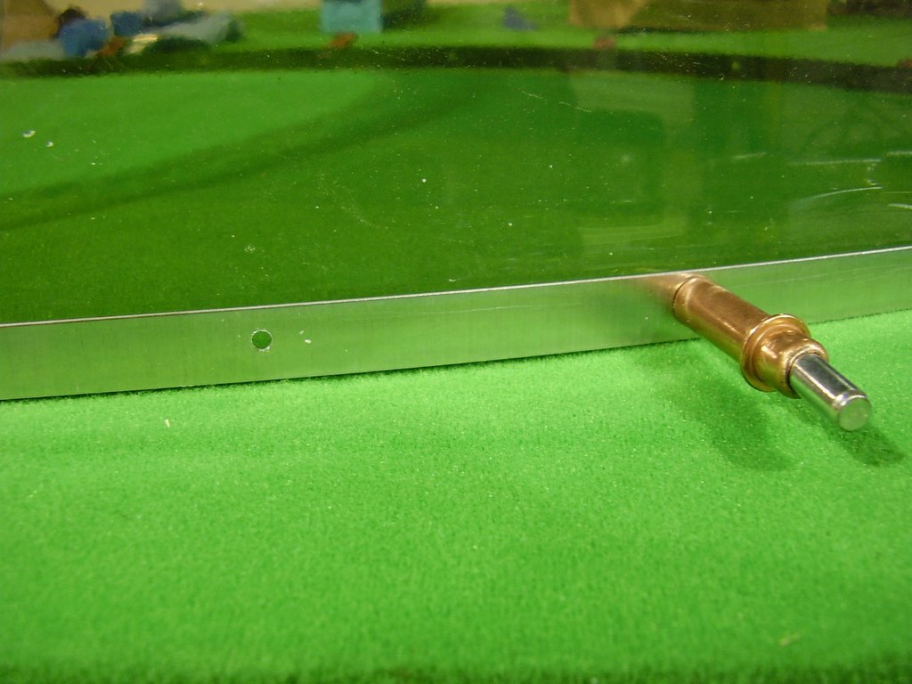
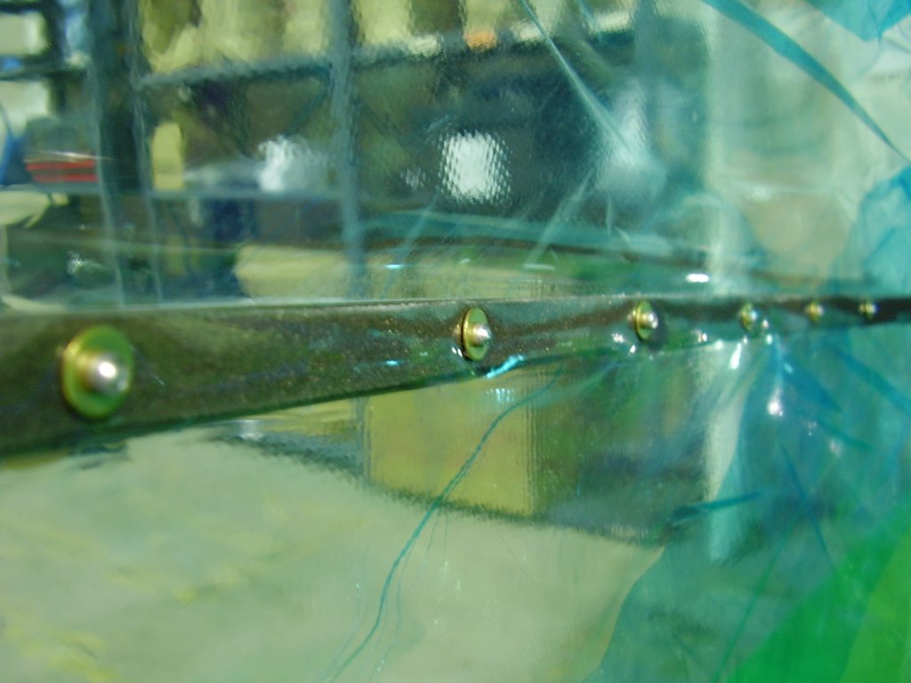
I started off by drilling the rivet holes into the aluminum strips. The manual says to start the holes a quarter inch from the end of the strip which will mount at the tip of the nose. I decided to start the holes at 3/8" to allow the first hole to be used by the screws that will hold the plastic block and pitot tube. This spacing is required to give enough room for the pitot tube between the screw heads.

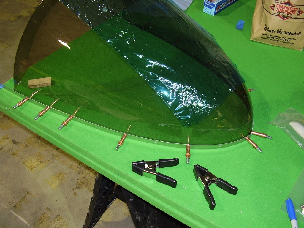
Once the holes were drilled into the metal strips I used clecos and clamps to help transfer the hole to the top half of the nose cone.


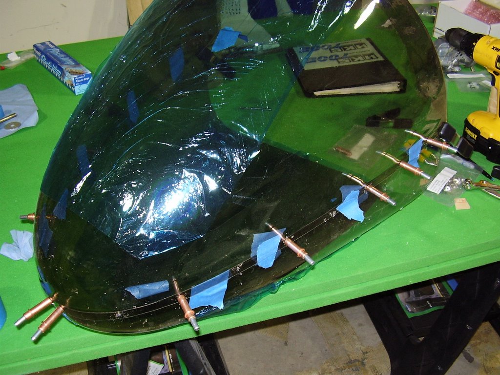
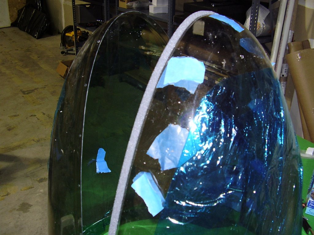
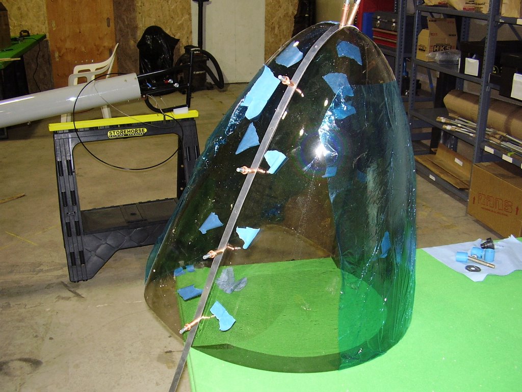
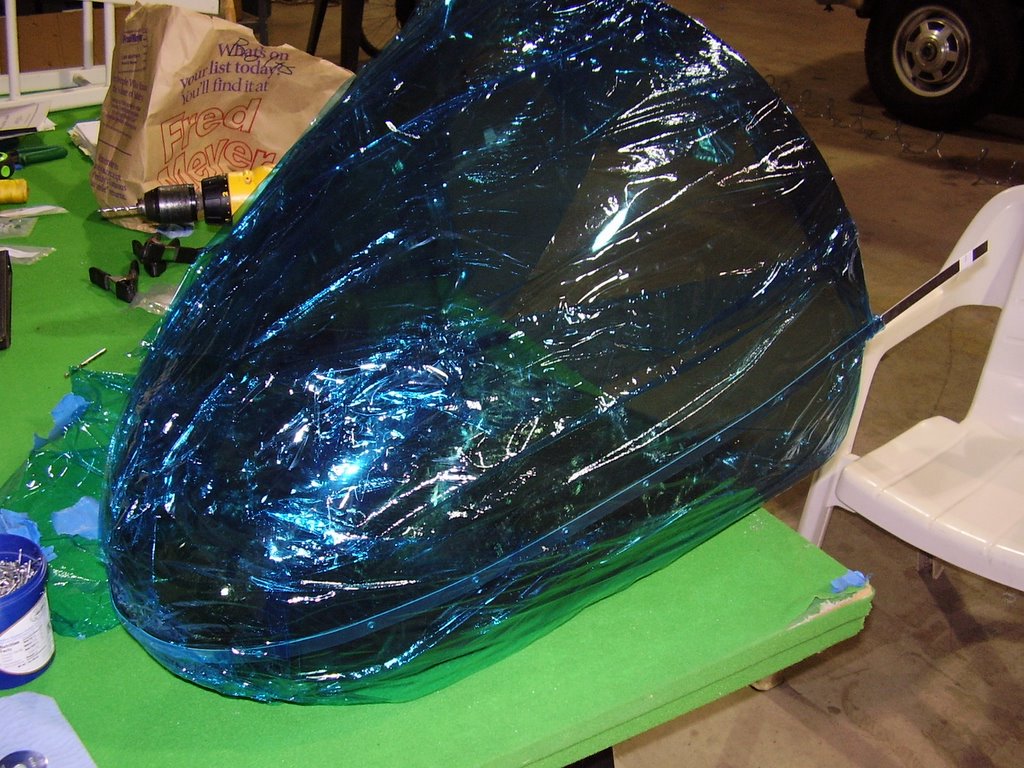
I used blue Saran (plastic) wrap to protect the nose cone lexan. I through out the plastic film that came with the pieces because they collected the lexan dust when I ground the edges down to the correct size. I was afraid the dust would scratch the lexan.


To give the metal strips a snug fit towards the tip of the nose cone I bent them into a slight curve. This was done by lightly hammering them with a rubber mallet over a 2" diameter rounded edge.


I then transferred the rivet holes to the lower half of the nose cone. This was tricky to do and get a tight fit without bulges.


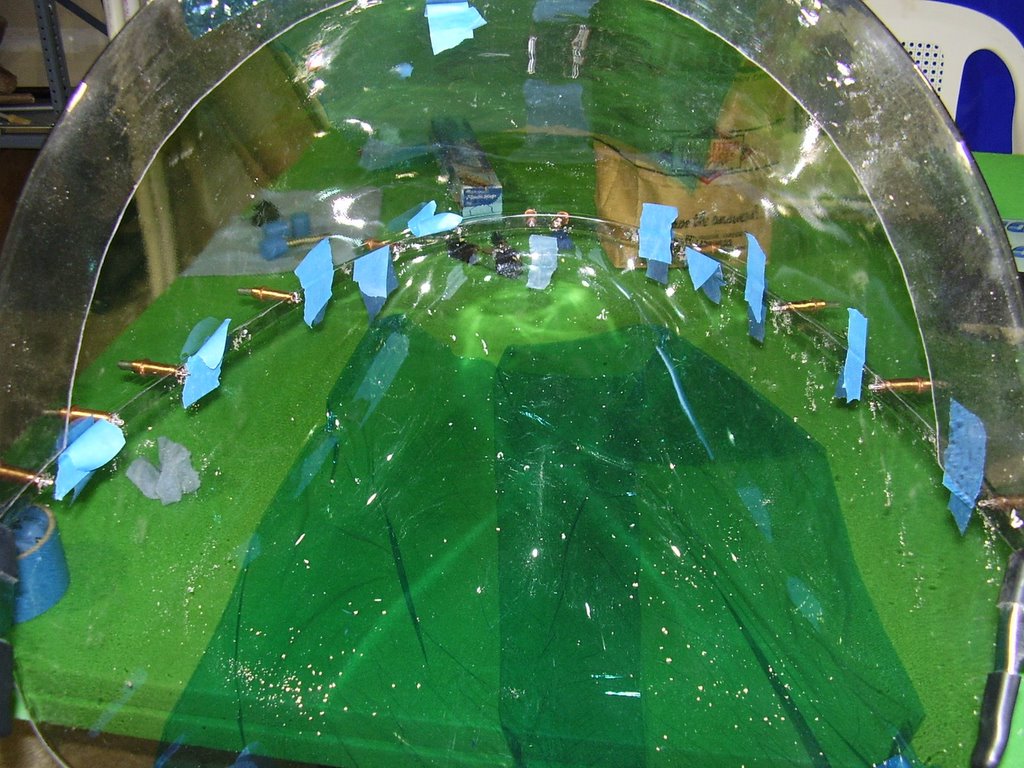
Prior to riveting the pieces together, I applied some foam to the lower nose cone half to fill any air gaps. I used the foam that the manual calls out to use as a door seal.


Assembled and ready to rivet...


Finished nose cone wrapped in blue Saran (plastic) wrap.


During the rivet process, two of the brass washers fell off. I needed to drill out the rivets to replace them (not fun) with the brass washers.

Wednesday, January 04, 2006

Rigging Flaps - 3 hours (178 Total)

I spent a few hours trying to rig my flaps to have the correct amount of droop to no avail.

During the process I noticed that I had bolted the teleflex retainer in the wrong hole in the left wing. There are two holes about an inch apart in the compression tube. The manual clearly states which hole to use within the text but doesn't reference it in the exploded parts diagrams. Luckily the holes were pre-drilled to the correct size for the bolt (I would have never been able to get a drill inside the zippered portal to drill out the hole). With considerable effort I was able to unbolted the teleflex retainer and move it to the correct hole.

Even with the teleflex retainers in the correct position, I still wasn't able to adjust the flaps to the correct droop. I adjusted the following components in many combinations...
  • Female Rod End - While maintaining min 10 threads
  • Teleflex Retainer - I've rotated this to point forward and aft but the change it makes is too great. I verified that it is mounted in the forward hole of the Flap Compression tube.
  • Insert Nut - While maintaining min 10 threads. I also tried removing the Insert Nut and using a lock nut but the change it makes is too great.
  • Flap Lever Teleflex Cable - I've adjusted how far the shackle bolts onto the threaded end of the cable.
  • Unihorn - I verified that I'm using the correct hole (there is only one hole left after the unihorn was cut down to size) and it is oriented in the same manner as the assembly drawing.

I will contact Rans and ask for their advice.

Monday, December 19, 2005

Oil Fittings - 0 hours (175 Total)

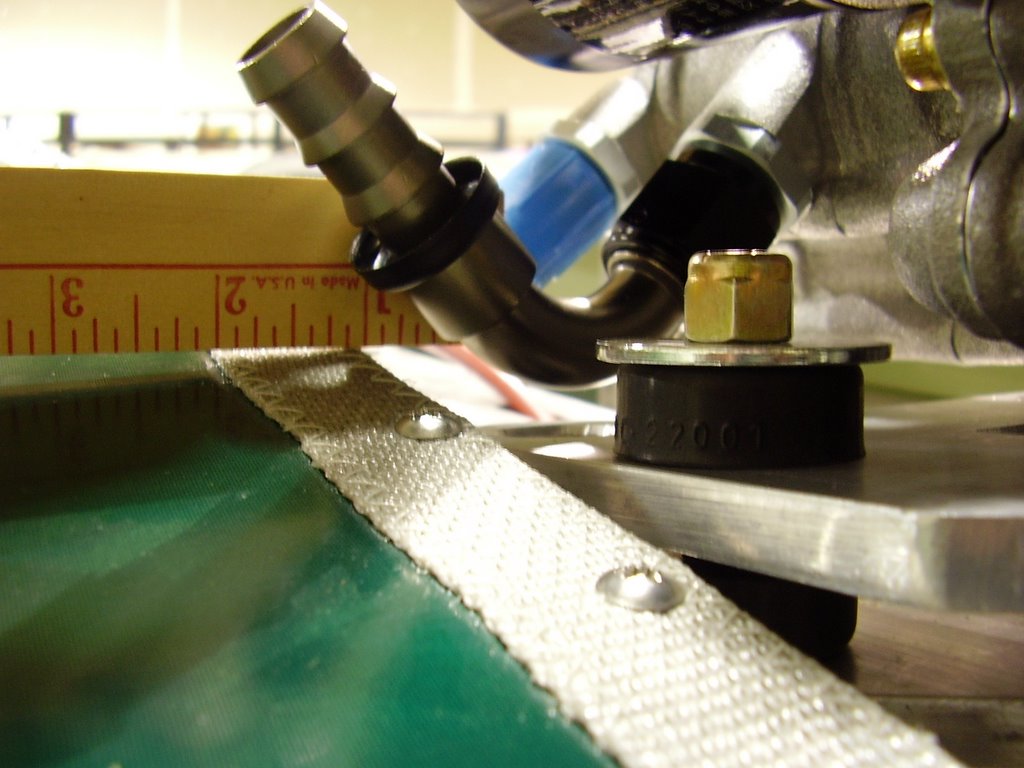
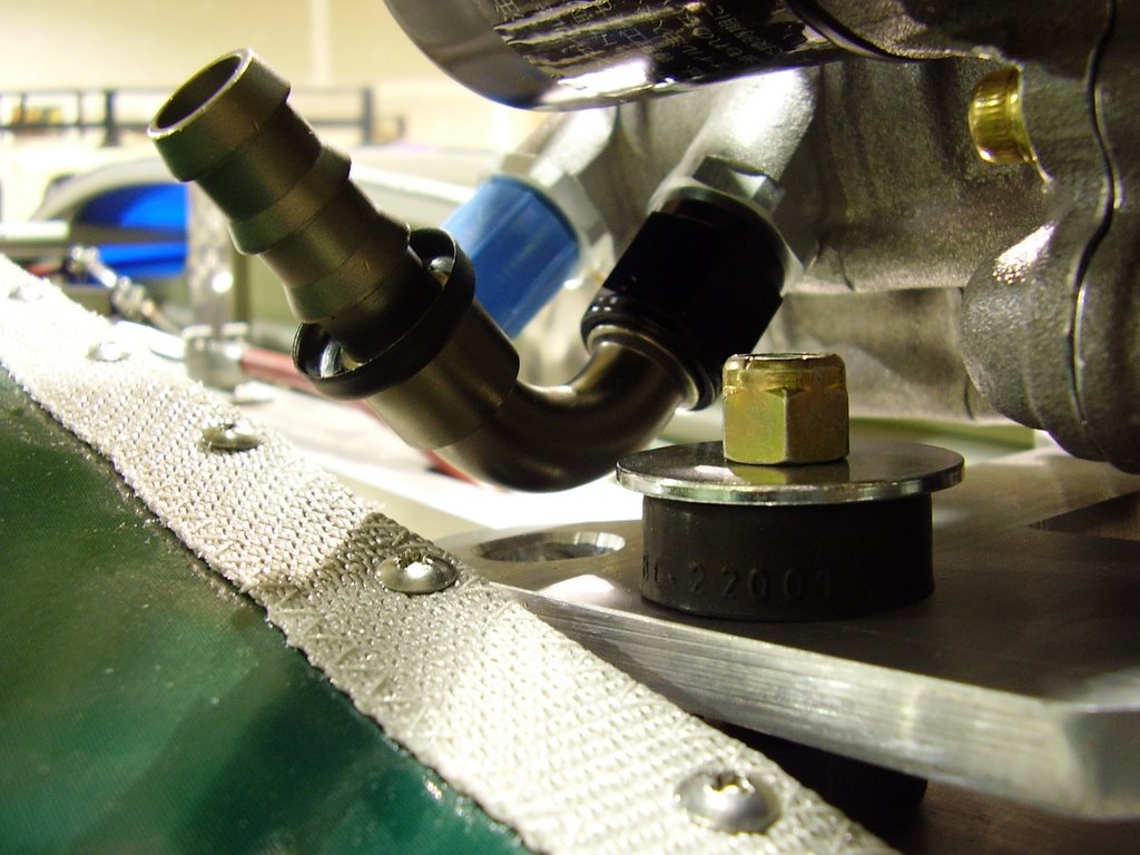
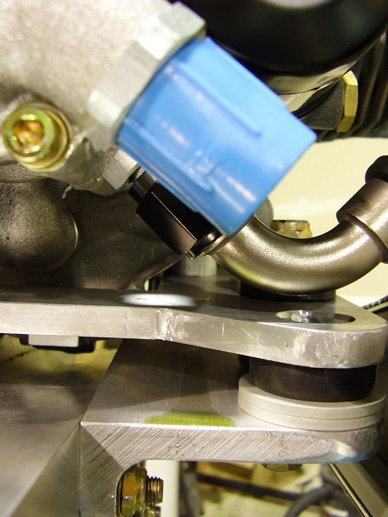
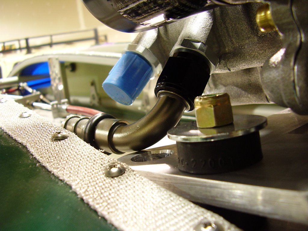
I received the 90 degree and 120 degree oil fittings today. It looks like there are severe clearance issues with either fitting and the engine mount. Hopefully the 150 degree fittings help.

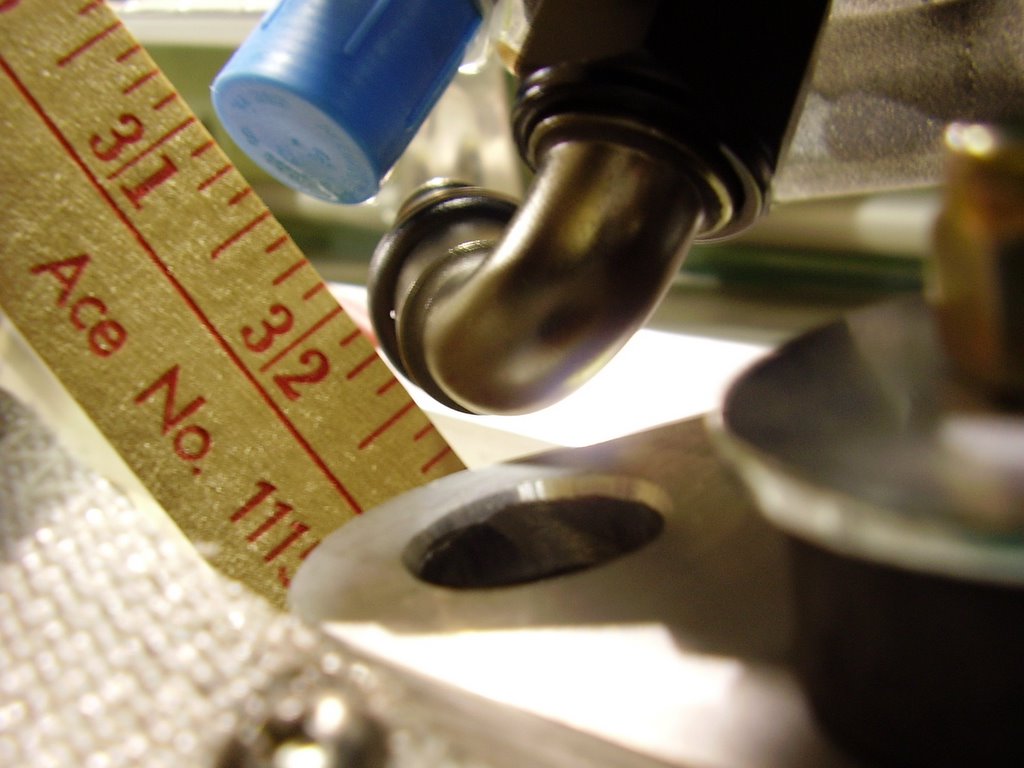
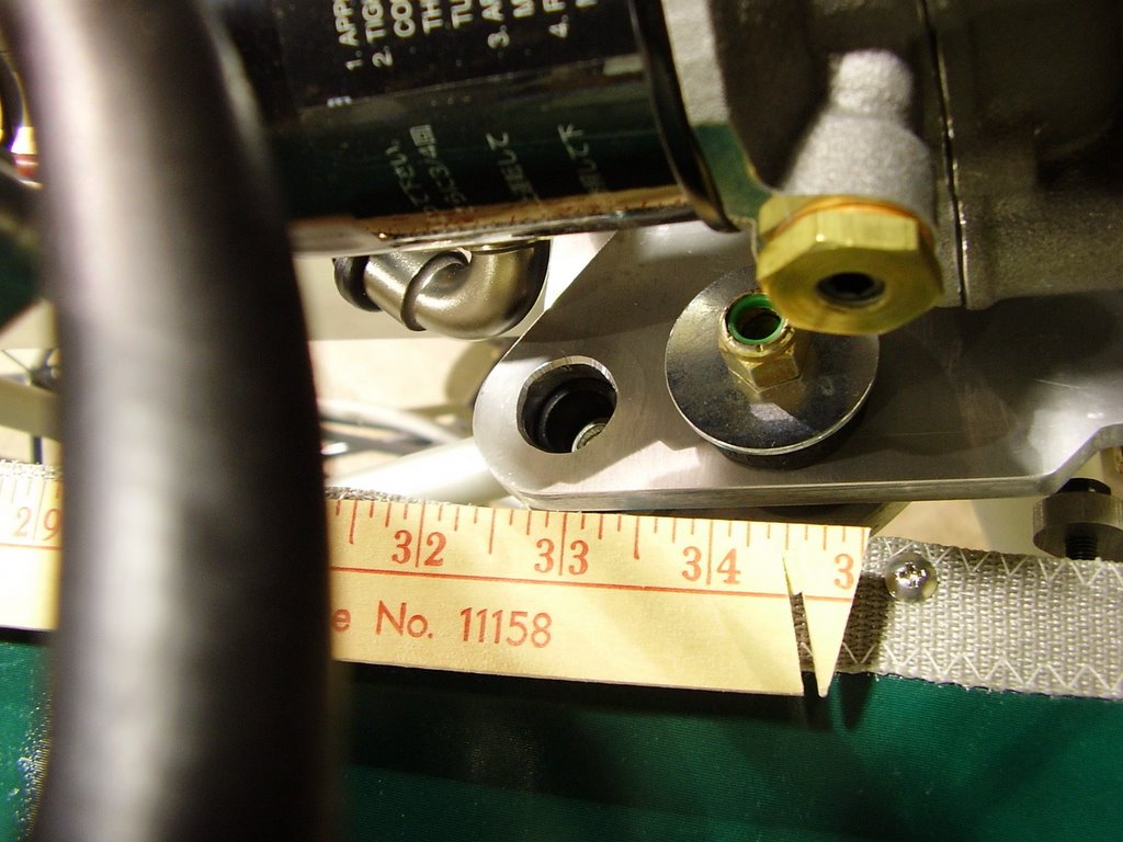
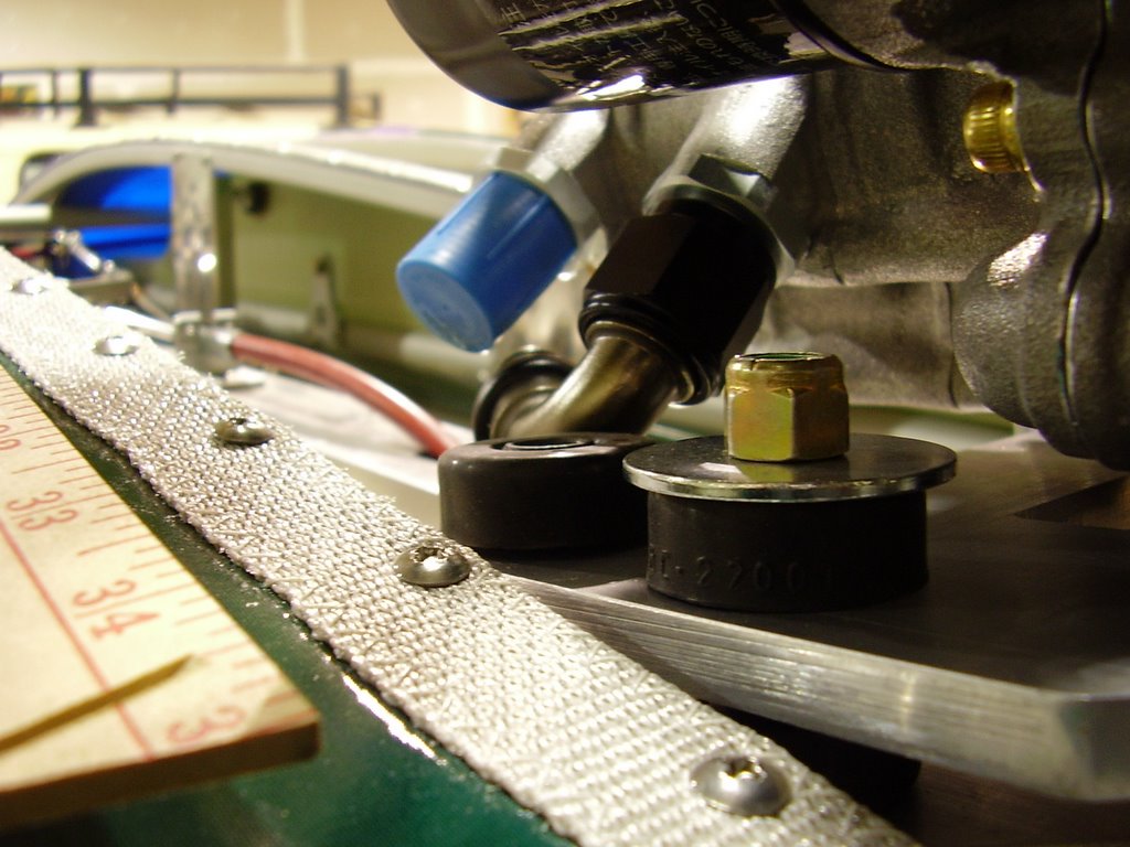
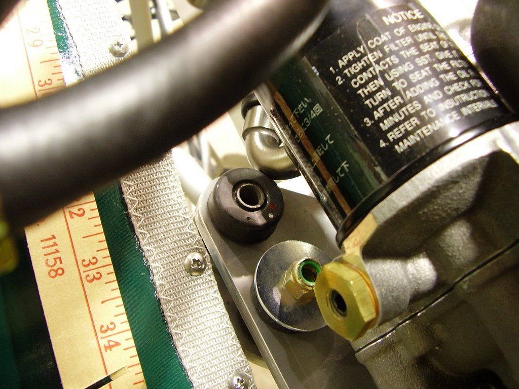
Below are four pictures using the 90 degree fitting. As you can see in the picture, the Barry mount is in the direct path of the fitting.


Below are a few pictures of the 120 degree fitting. This fitting has a little better clearance but the Barry mount washer will still have clearance issues. Even with the planned 1/4" increase in distance from the engine to the plate for the next rev of the mount, I don't think there will be enough clearance.