Tail Boom - 6 hours (127 Total)
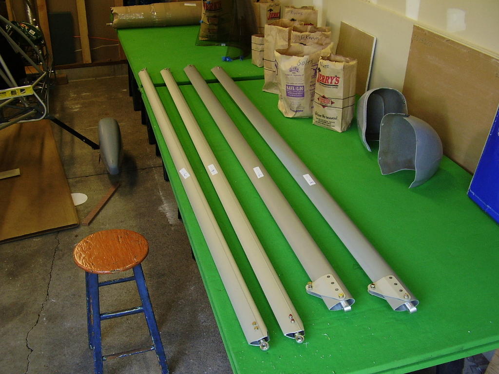
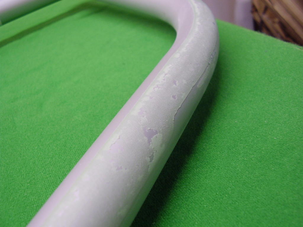
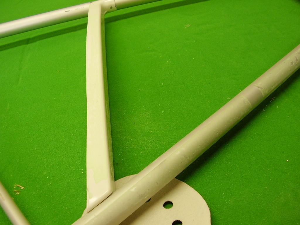
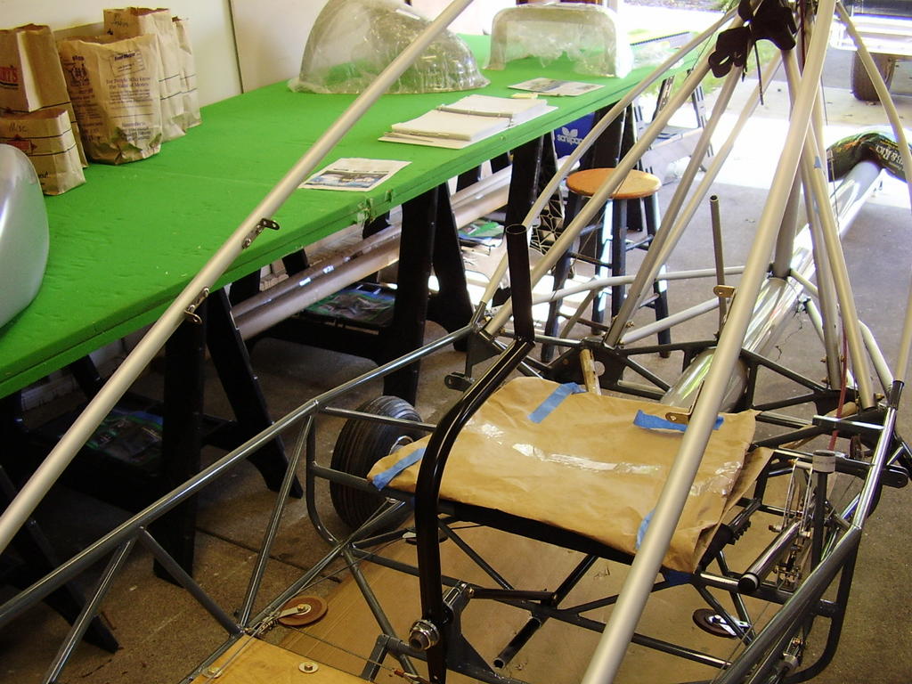
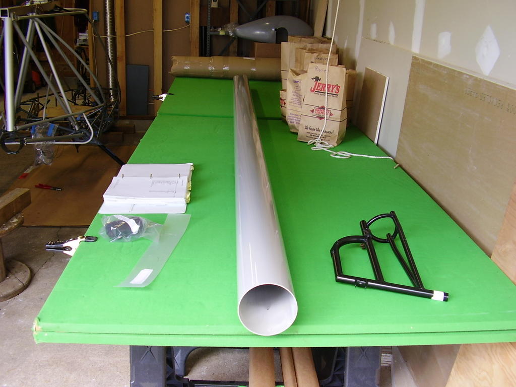
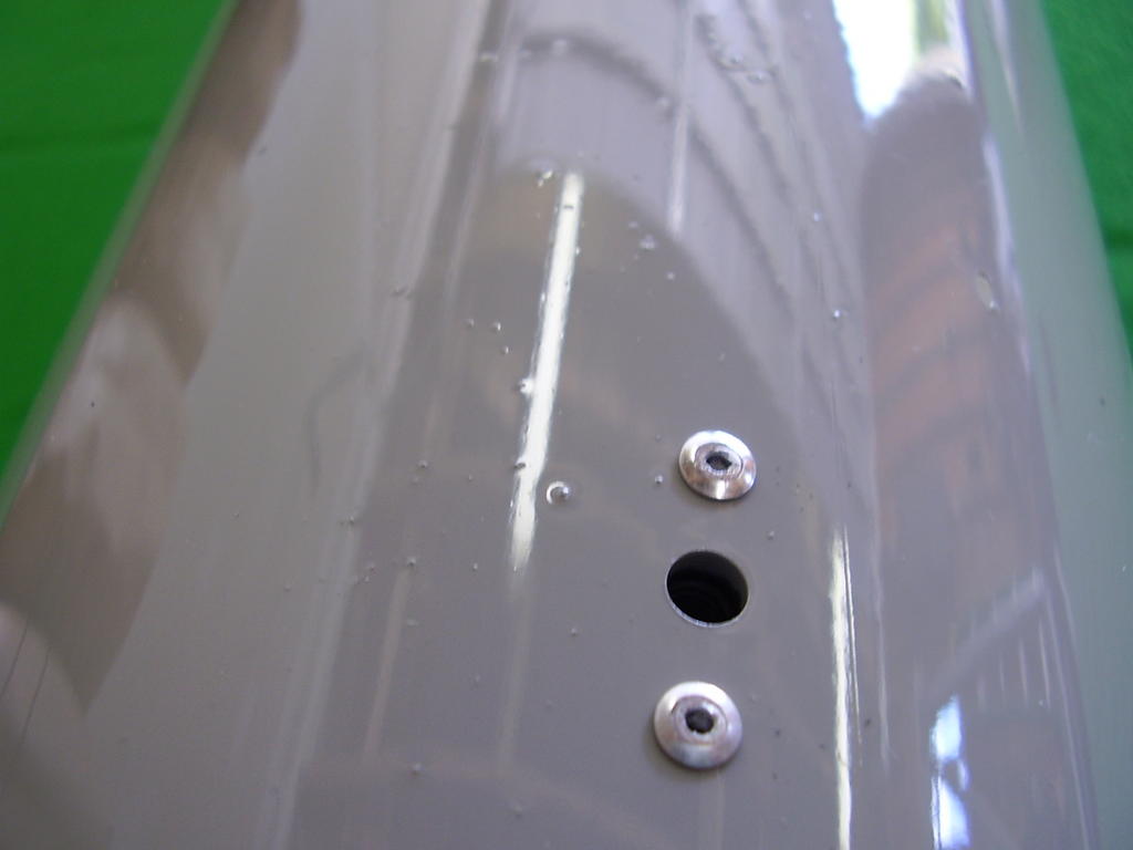
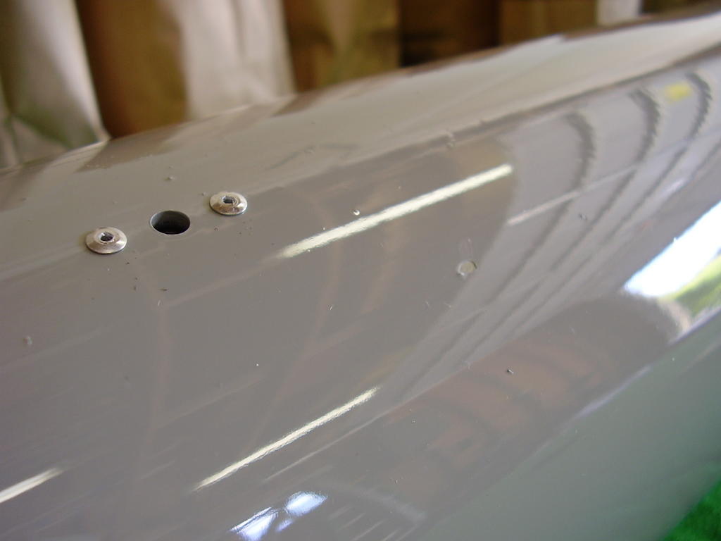
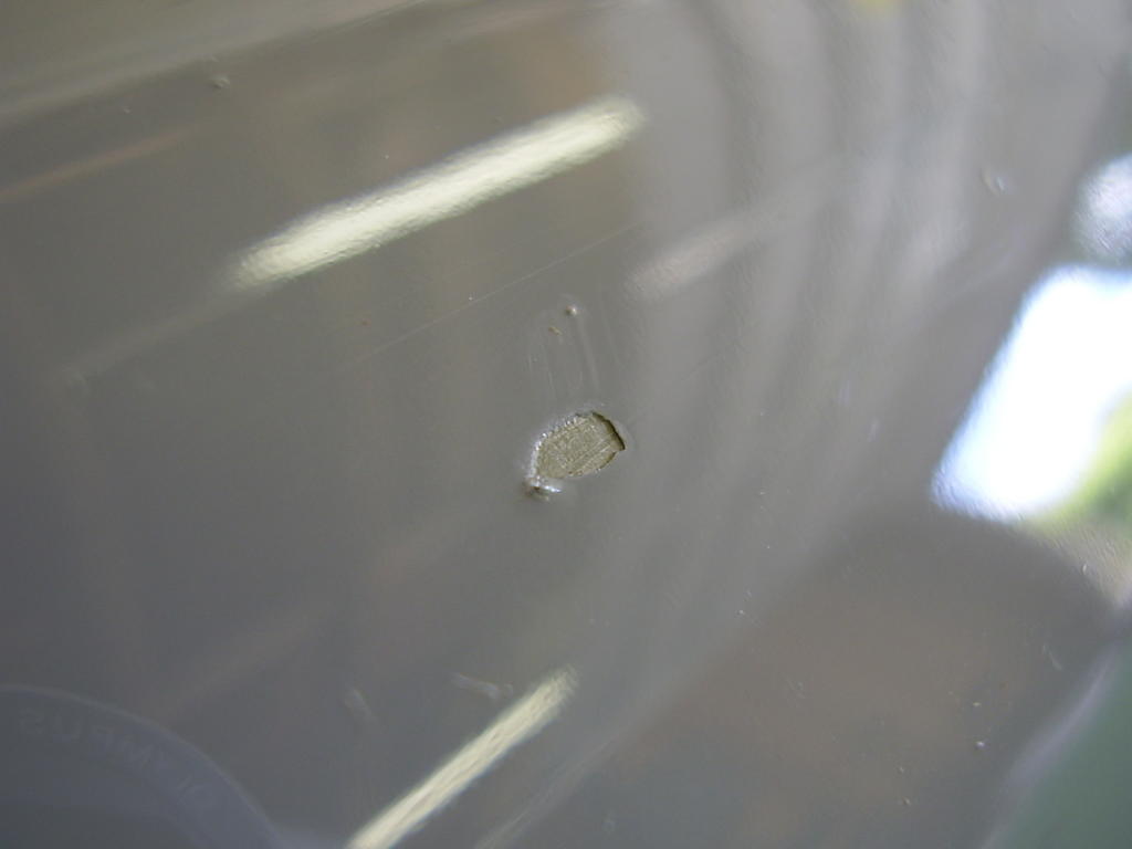
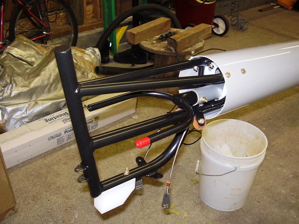
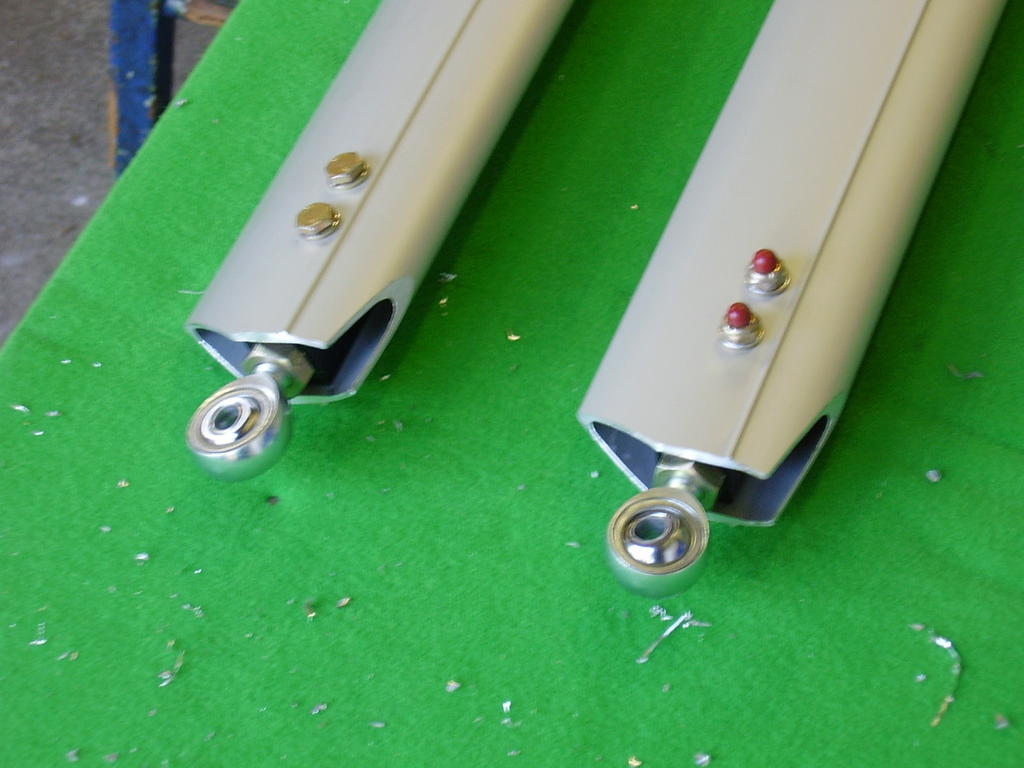
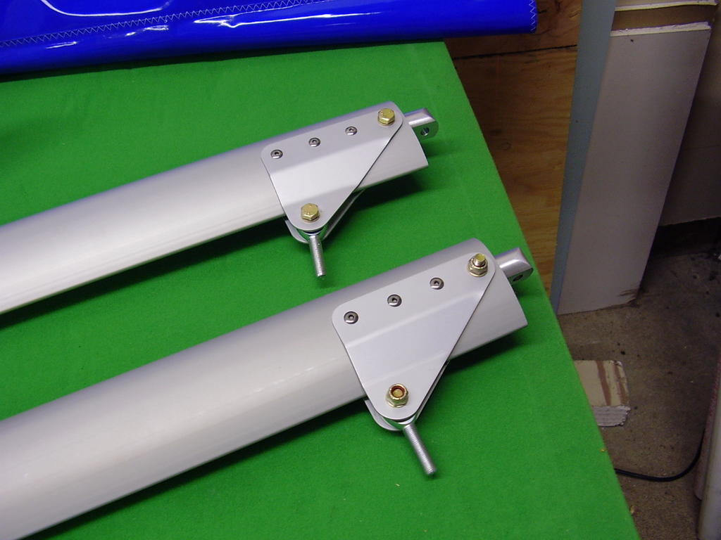
Today I installed the tail boom and related components. I started off by installing the four nut plates into the tail boom. I screwed up on one of the rivets and need to replace it with another 40APR1/8. I noticed some bubbles and chipping in the finish near the nut plate holes which I took some pictures of.
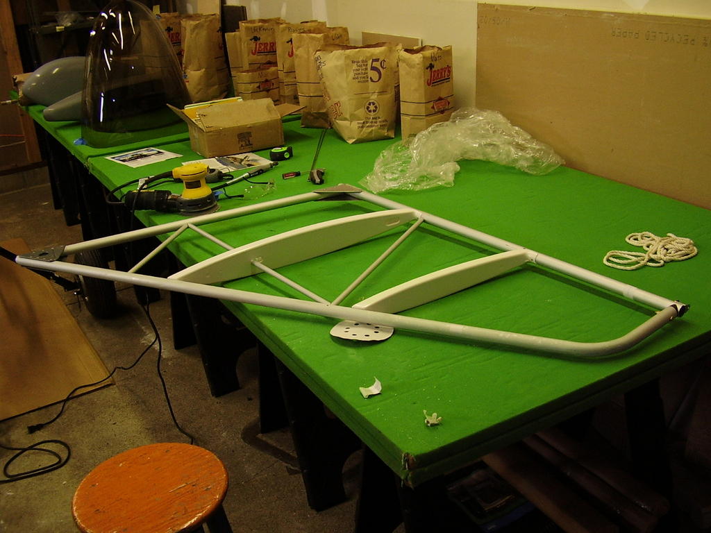
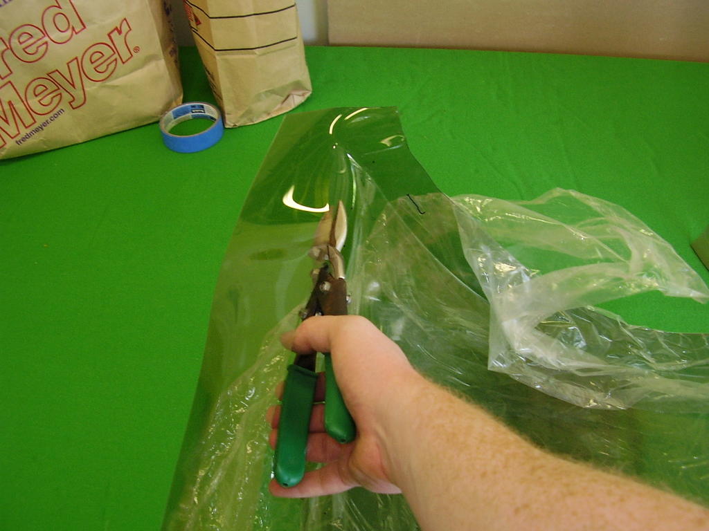
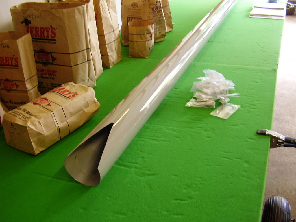
Prior to installing the tail boom, I verified that it had a reinforced layer on the inside. The reinforcement started at 33 13/16 inches from the front and ended 61 7//8 inches from the end.
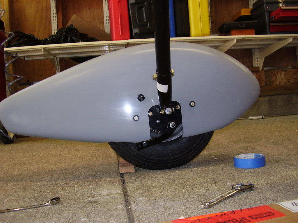
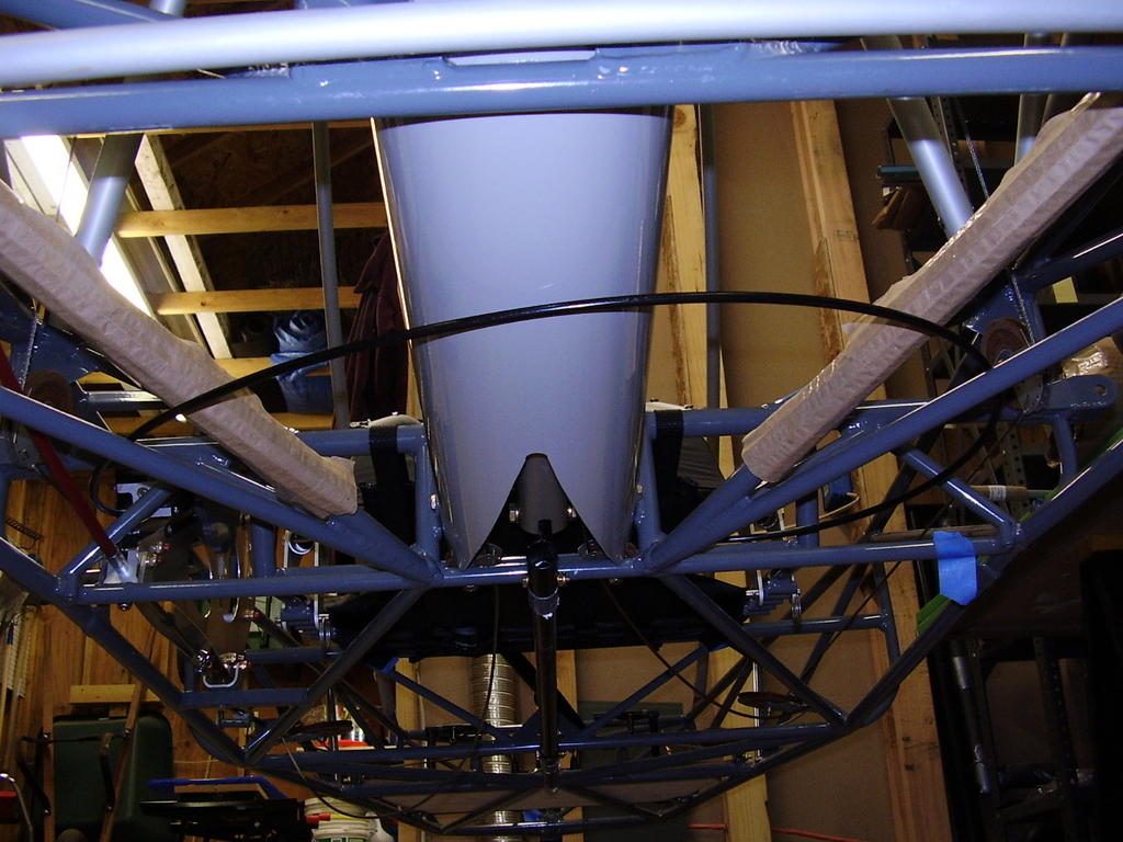
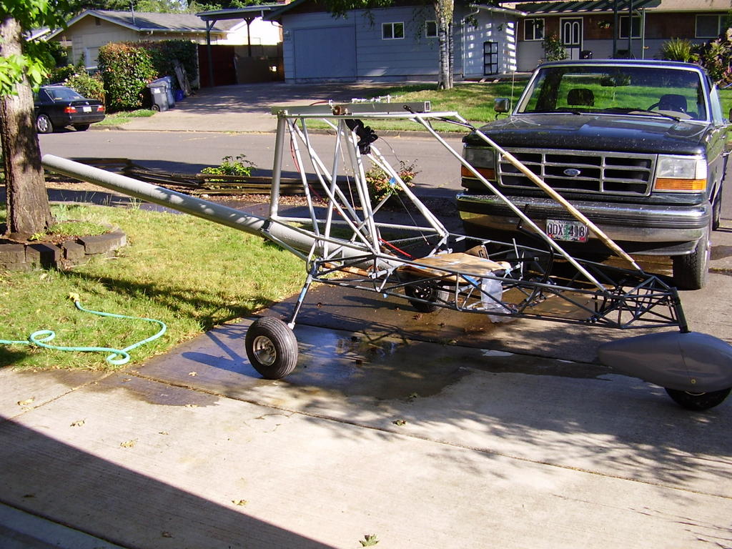
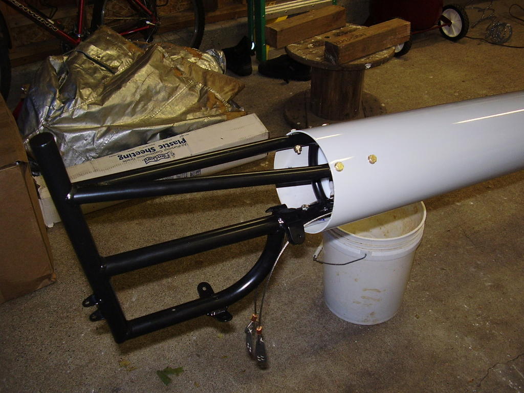
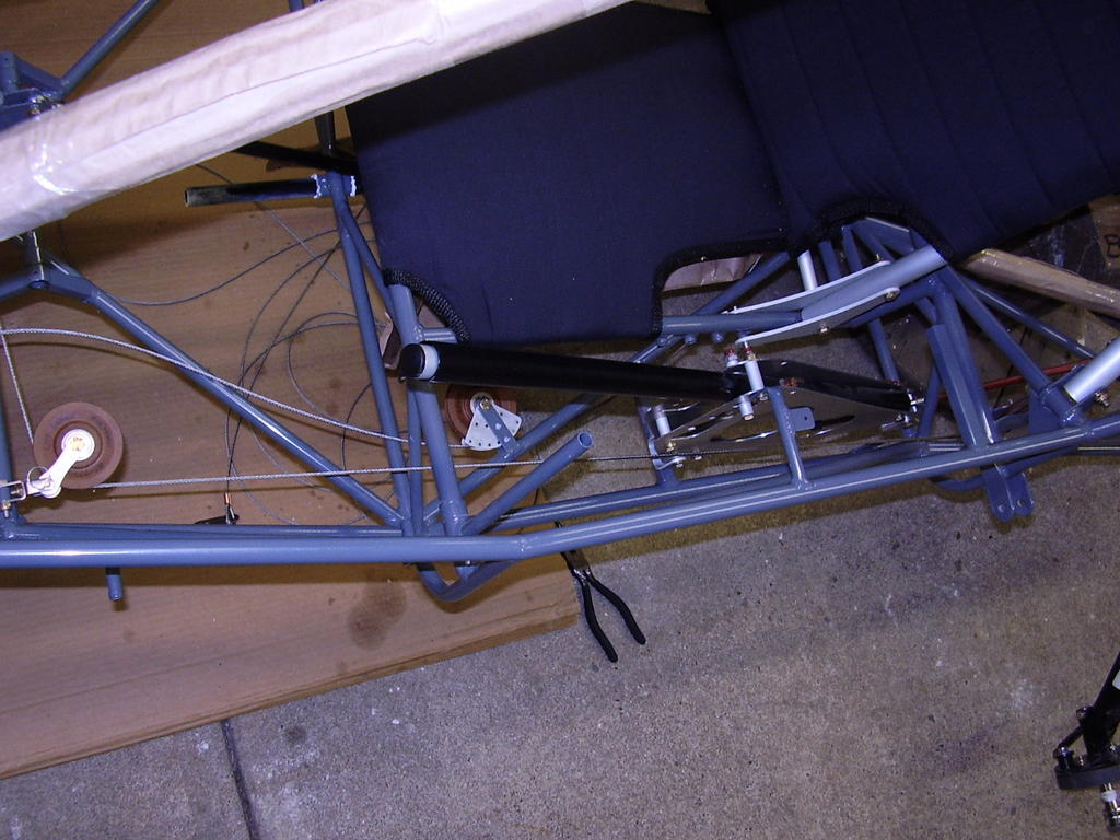
I installed the tail boom into the chassis with the recommended Vaseline. This worked very well but cleaning the Vaseline off took a significant amount of work. I used gasoline and paper towels to wipe off the majority then washed the tail boom with dish soap and water. Rans told me afterward that 409 works well for cleaning off the Vaseline.
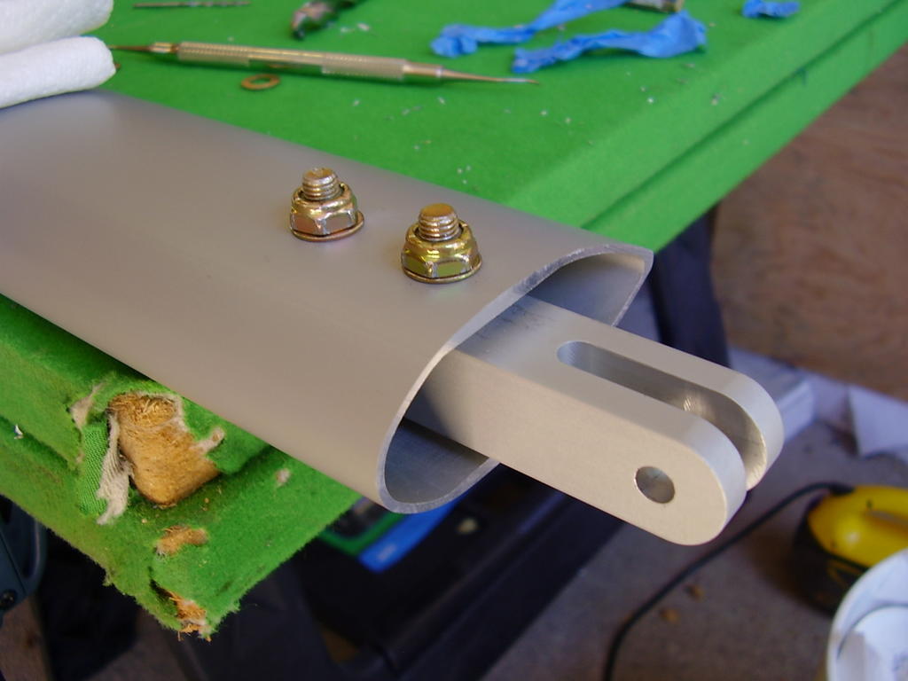
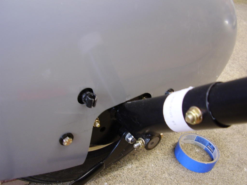
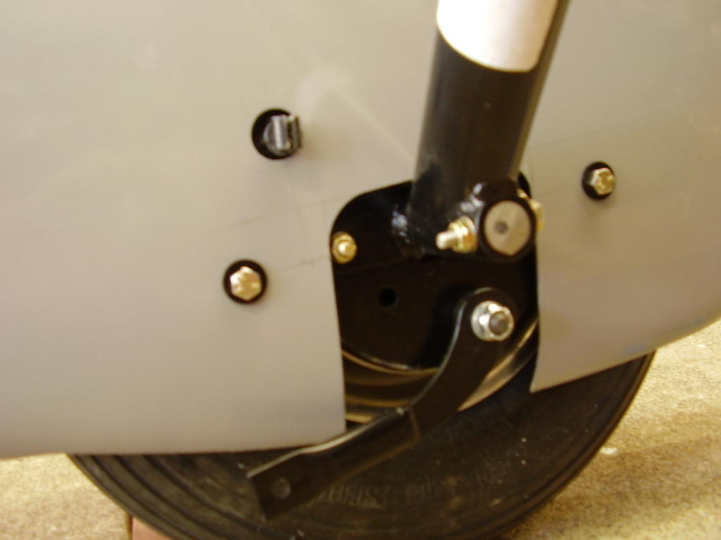
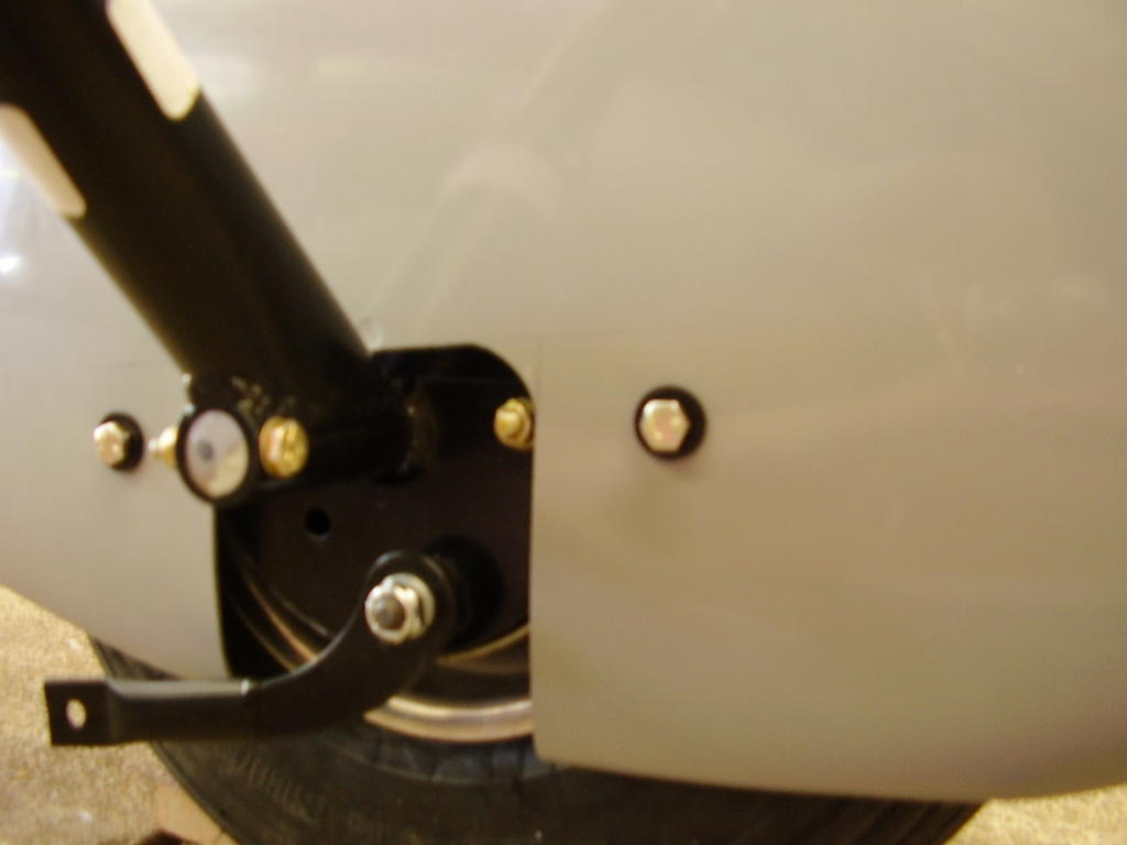
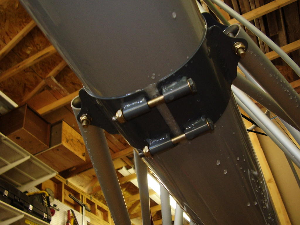
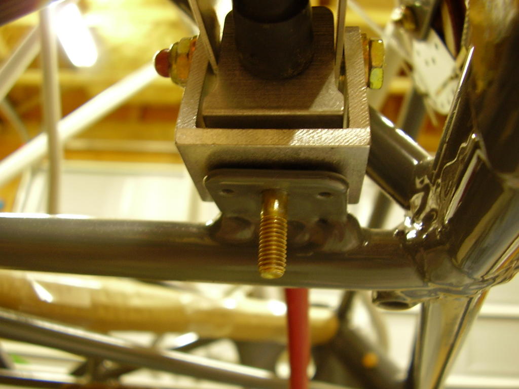
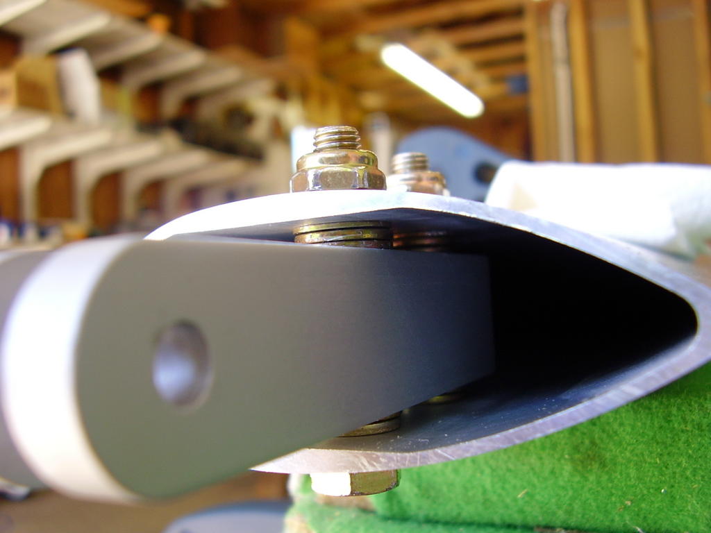
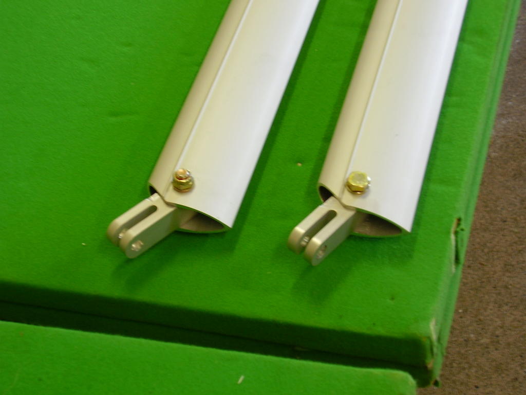
I did not glue the lexan strip that is used in the tail boom bracket. I used a piece of wood to pry the bracket apart so I had room to install the lexan strip after the tail boom was installed.
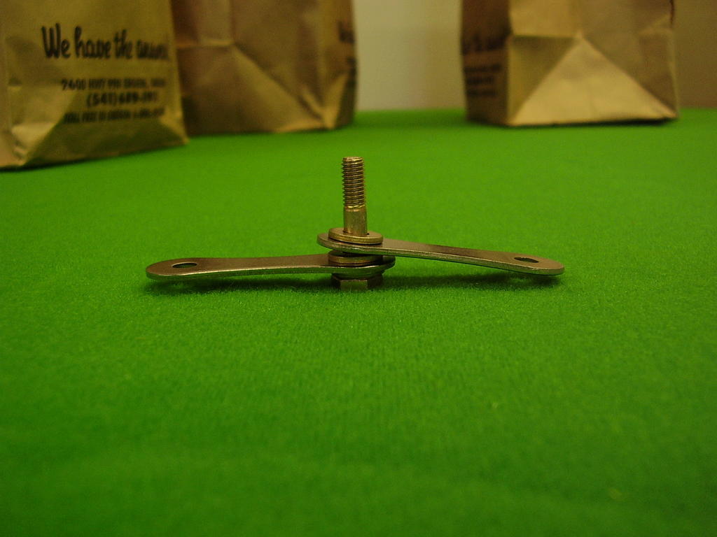
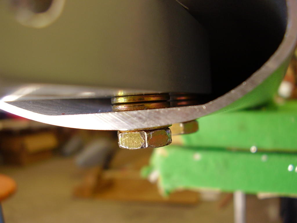
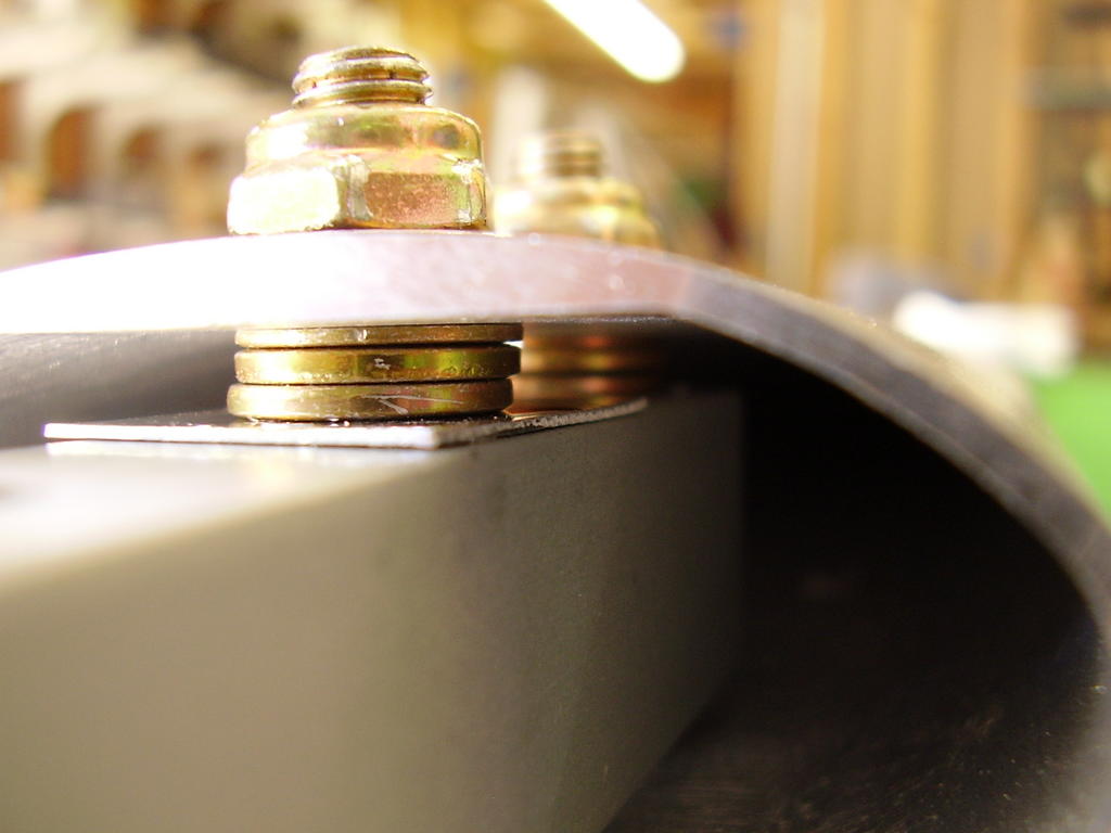
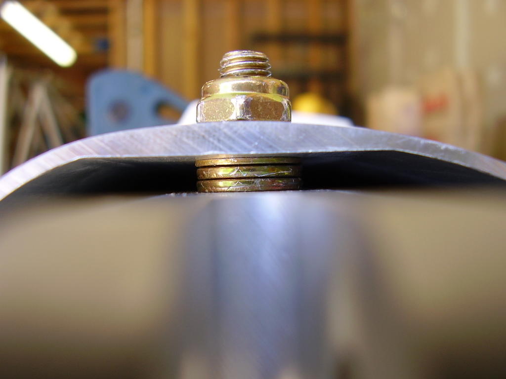
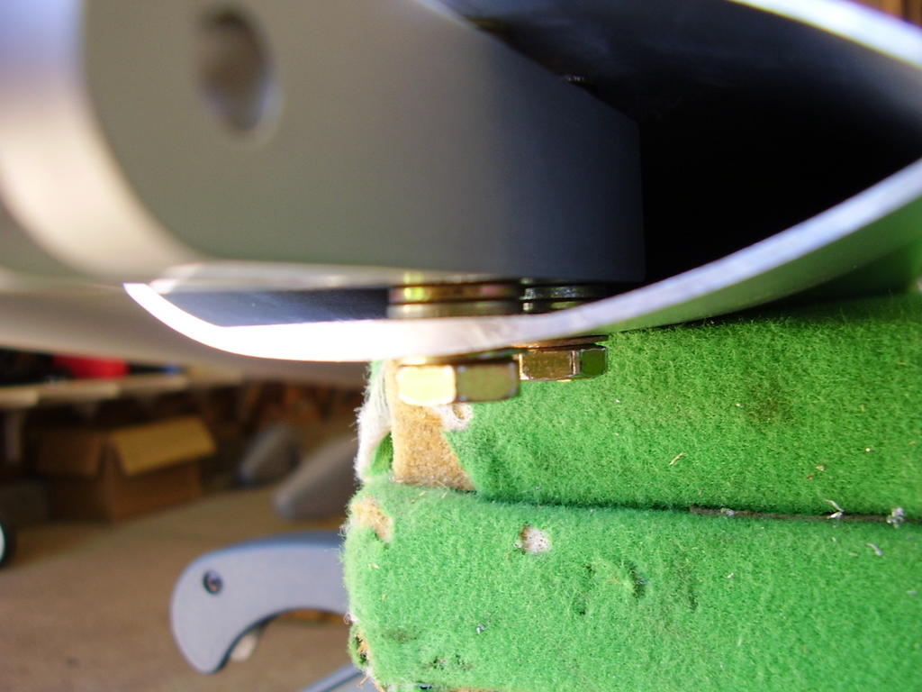
My kit did not come with the (2) AN4-27A bolts that are suppose to be used in the tail boom bracket. I assume I didn't receive enough (2) AN365-428A nuts or (4) A960-416L washers either. As a temporary bolt, I used the ALP (painted head) bolts that were too long for the wing.
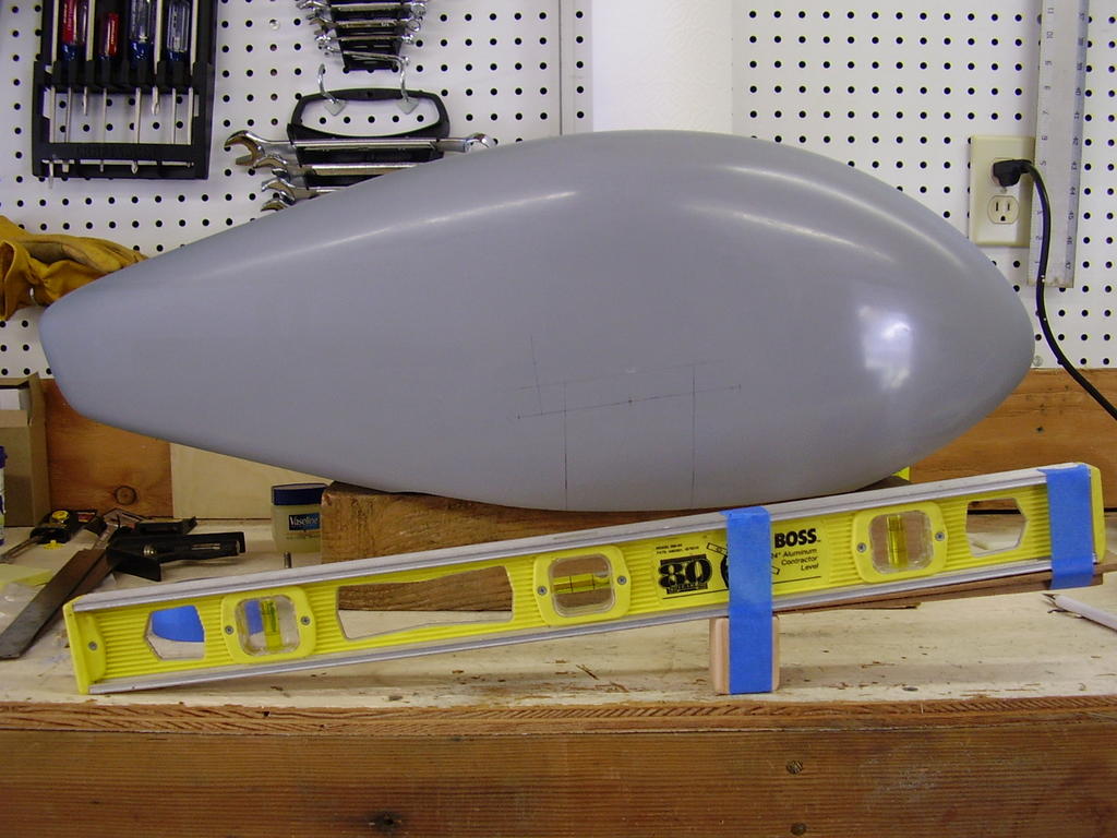
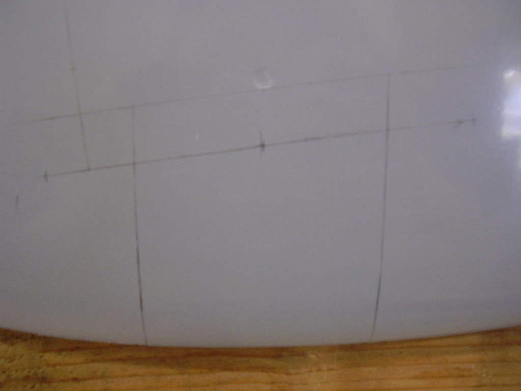
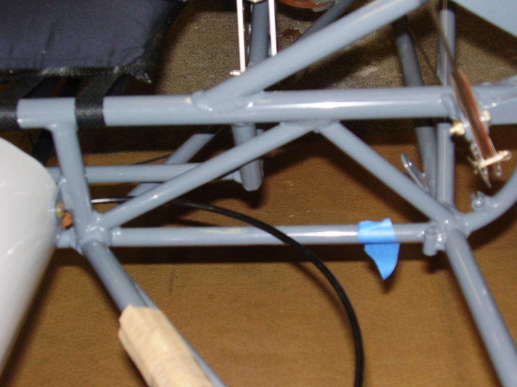
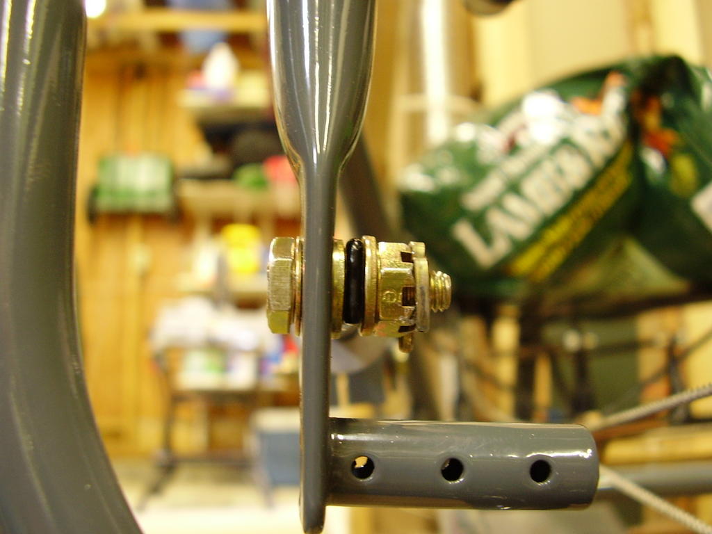
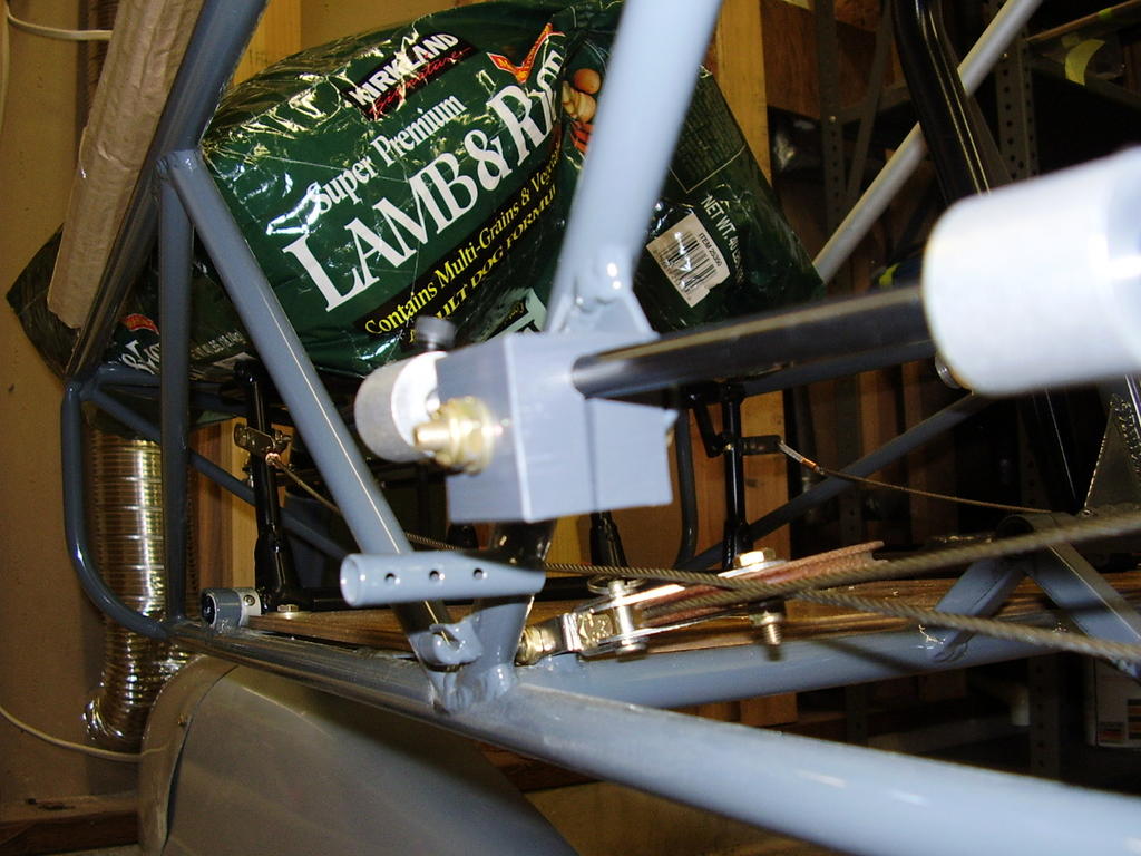
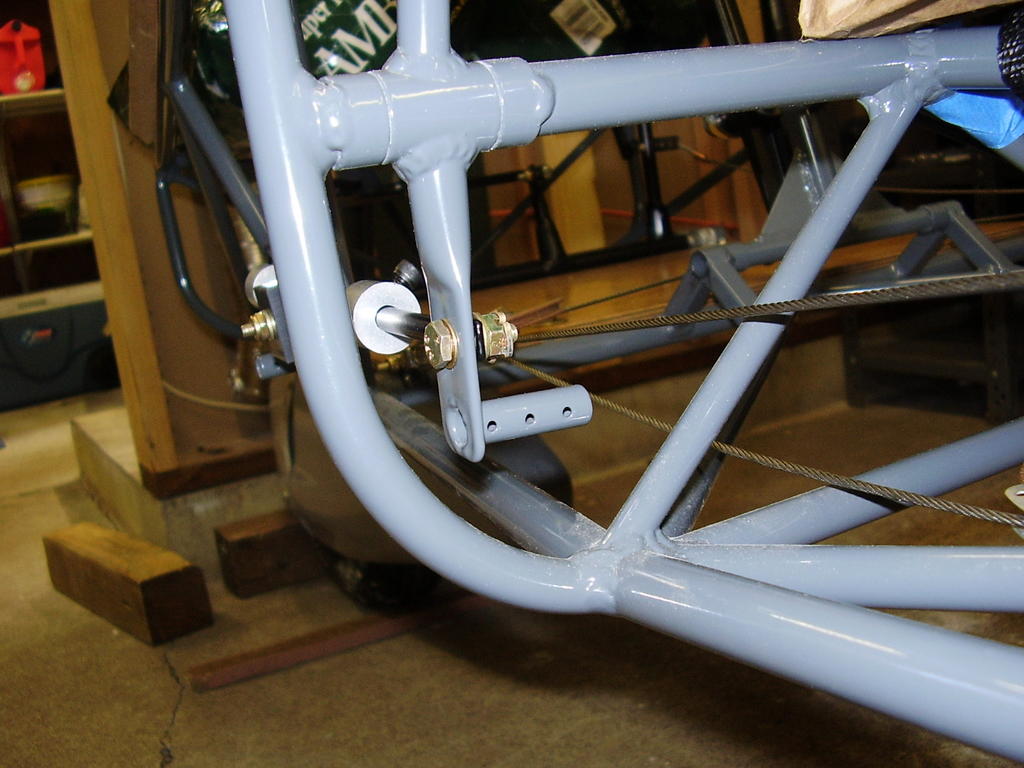
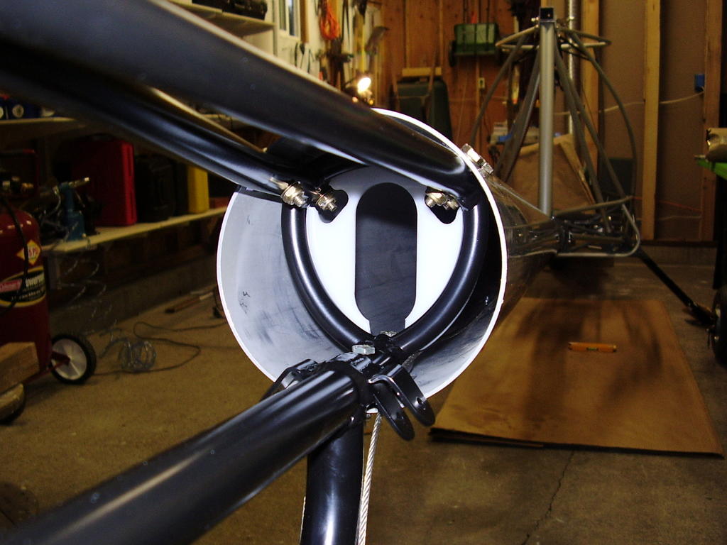
I then level the chassis which was difficult to do since my seat bottom cushion was installed. The manual recommends putting a level across the seat truss to level the chassis. After leveling, I found the bottom of the tail boon and drilled three holes for the tail boom extension and horizontal stabilizer cable tangs.
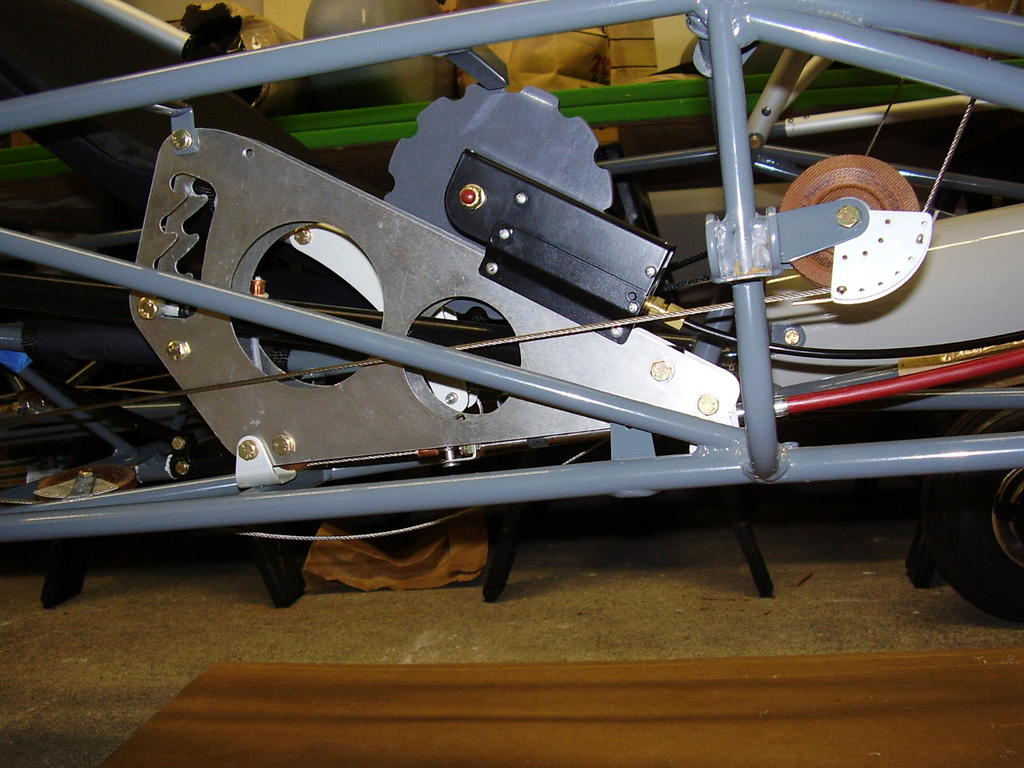
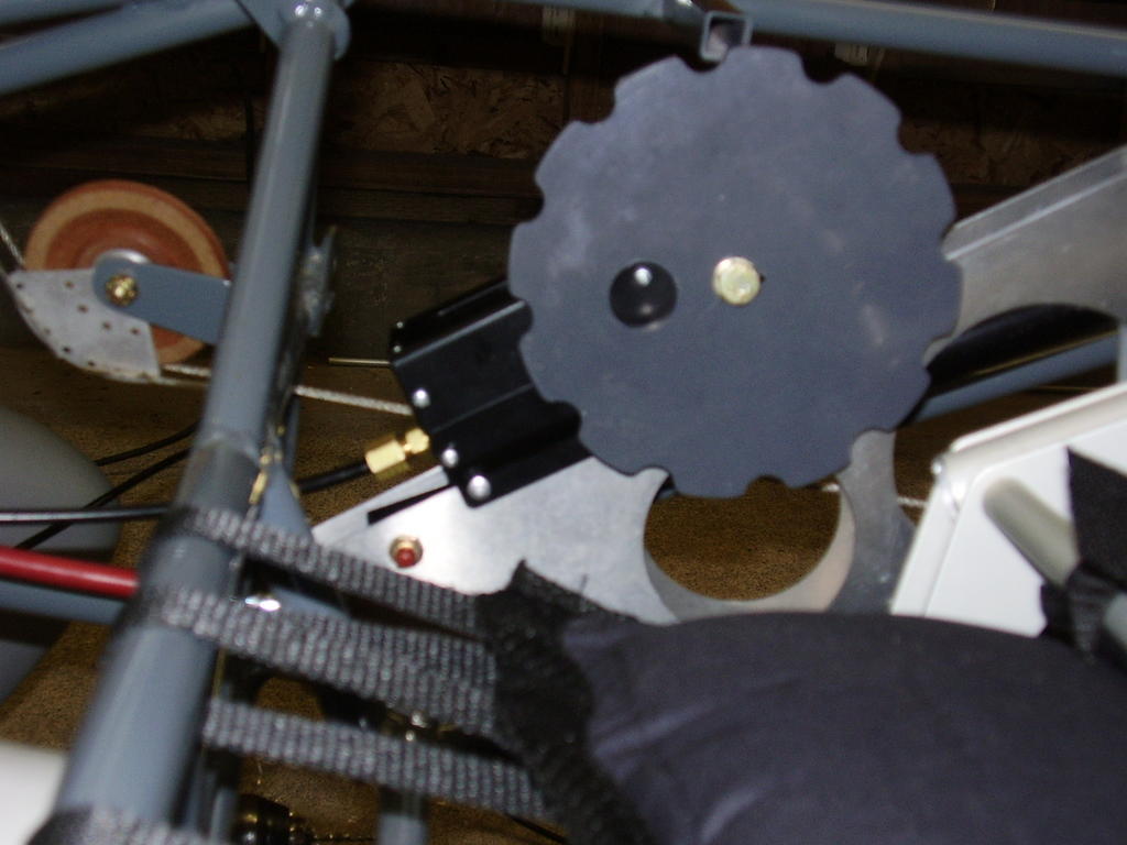
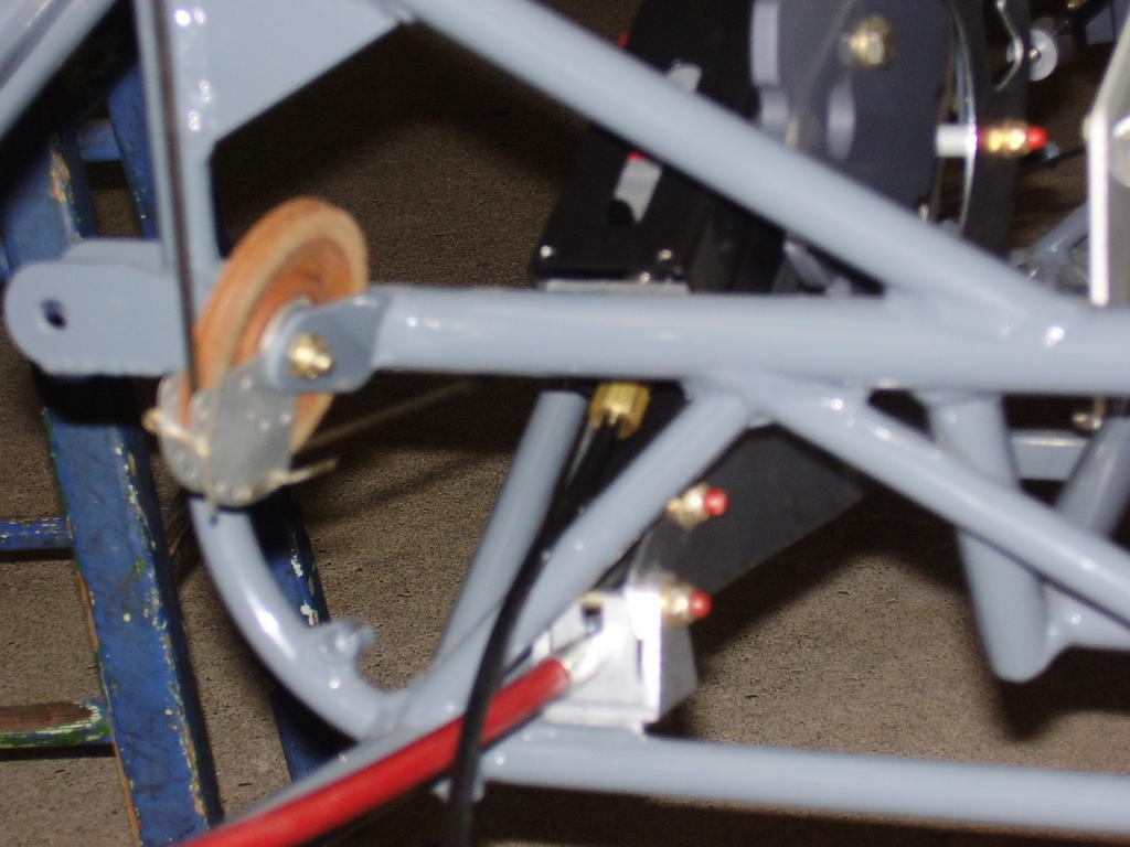
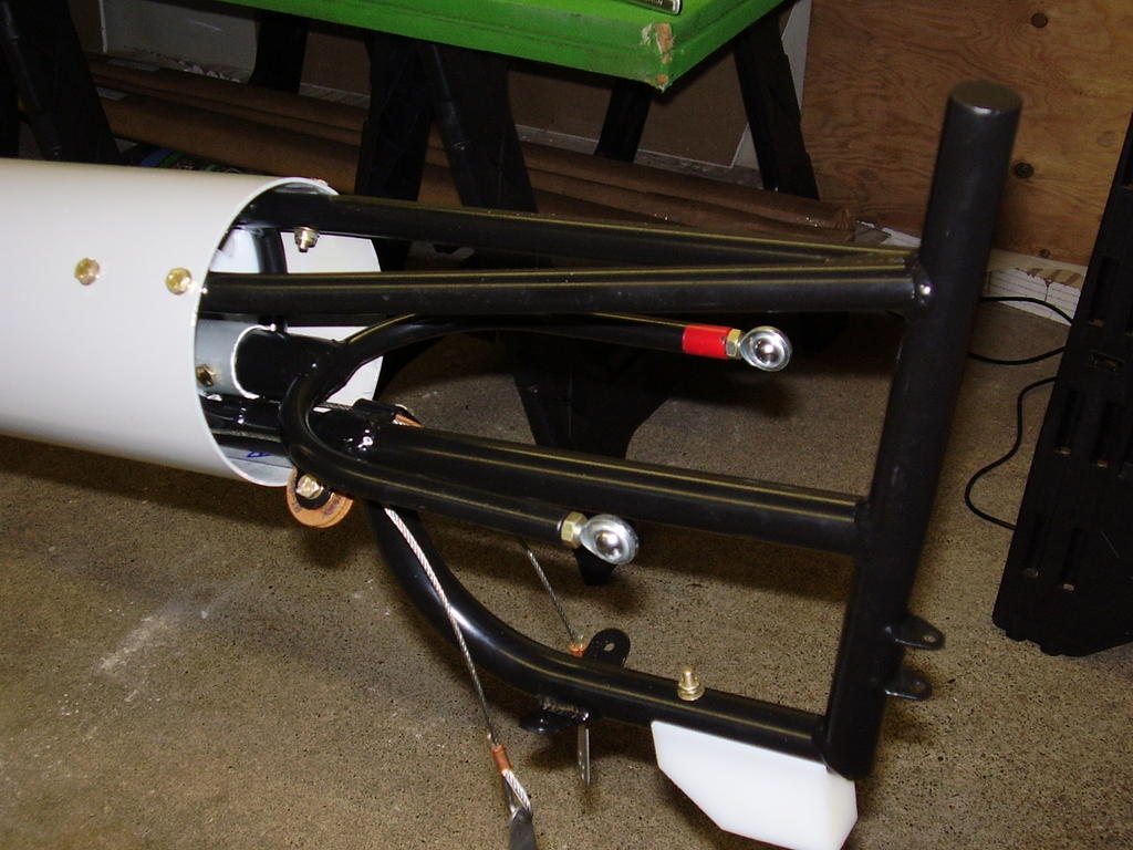
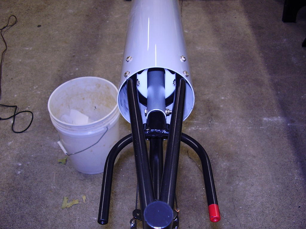
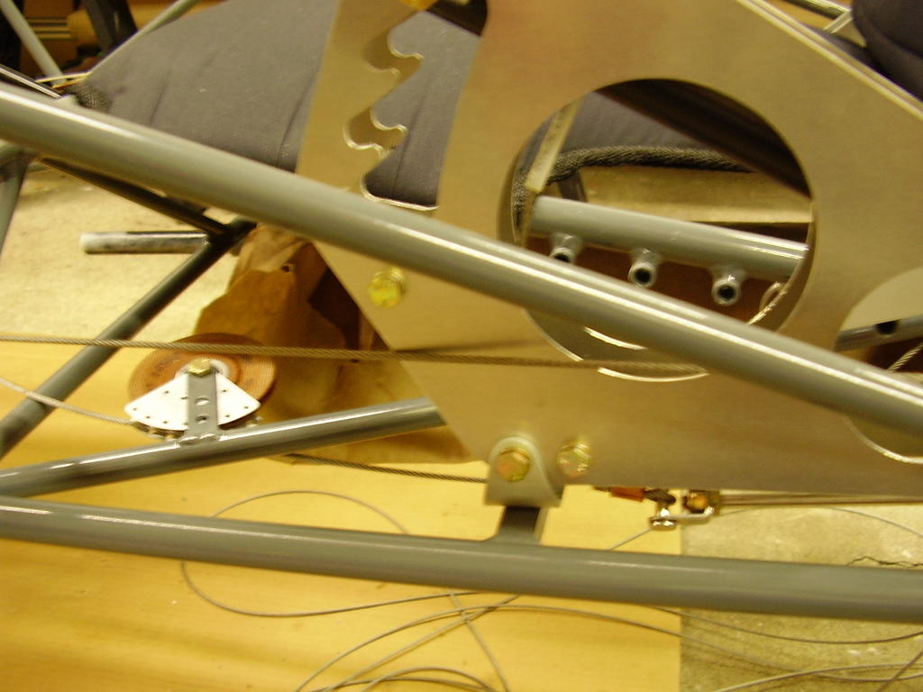
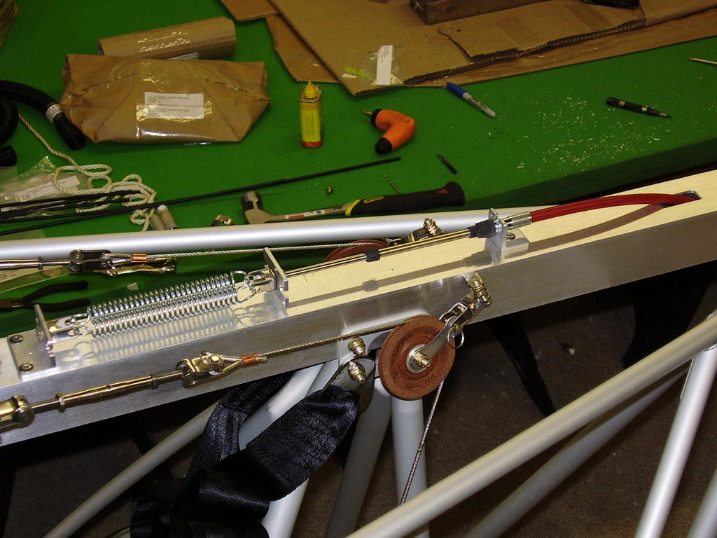
I then installed the tail boom extension. The elevator push pull tube guide needed significant modification to allow the inner nuts to be accessed with a wrench. I also installed the rudder pulleys and skid block.
I ended up removing and reinstalling the tail boom extension at least three times for different reasons. The last reason was to install the larger elevator push pull tube. The manual isn't clear about when to install this and how. It also doesn't mention where on the push pull tube the foam rubber insulator is suppose to go. I placed it in the middle of the tube.
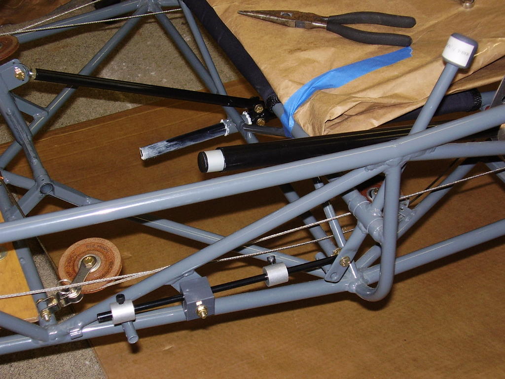
Lastly, I installed the elevator horn and connected the large elevator push pull tube to the 5/8 inch elevator push pull tube that's connected to the control stick. I noticed that the large elevator push pull tube is double re-enforced on the front end but not re-enforced on the back end.